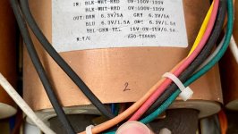
The 1085 needs 6.5vdc, no ripple to support 5vdc.>I wonder if my plan is feasible or the 6.3vac is a bit too low for 5vdc output?
The in cap of your circuit gets 8.8vdc peak so it would work with a large cap and and no 300B.
That will need an extremely large input capacitor to have low enough ripple for the reg to not drop out.
I would try two identical reg circuits, each on a separate secondary, to reduce all the component stress.
Those diodes are only 4A though, use 30A rectifier blocks instead. You may have to use voltage doublers.
Regs need significant heat sinking. Maybe AC filaments aren't really so bad.
I would try two identical reg circuits, each on a separate secondary, to reduce all the component stress.
Those diodes are only 4A though, use 30A rectifier blocks instead. You may have to use voltage doublers.
Regs need significant heat sinking. Maybe AC filaments aren't really so bad.
Fine regulator (today often fake) but in this case it has too high dropout voltage of 1.3V typical AFAIK. It will require ultra low Uf Schottky diodes/LT4320 and overdimensioned filter caps anyway to have least possible ripple voltage. Think of 22,000 µF 16V or larger. Do not use "any" diode with supposed audiophile properties as apparently common in the tube world. See the threads here, it just does not work out well. They need to deliver current to a light bulb load and need to have lowest possible Uf to diminish losses and avoid heat. The load is the easiest they could ever meet in their life. If in reality you have a little too much input voltage then a 25..30A normal Graetz bridge may be exactly the right one to have planned losses.
You may need Tombo56 R25 or similar uLDO designs. A member there sells 6.3V AC to 5...6.3V DC PCBs for this exact purpose. You may need to divide power over 2 boards for aforementioned reasons.
Our grand dads did a good job with AC filaments. Way simpler but so was the grid without solar and wind energy.
* Note: you can NOT use the 1.5A winding in parallel to the 5A windings!! If you know the loads current (a very relevant number) you could possibly use 1 x 6.3V 5A per branche so 1 regulator board per branche.
Last edited:
Yes, I will use 2 separate regs for each secondary. How much large capacitance should I at least aim for? I will replace those diodes with schottky.
It's a P-P design, so maybe AC filaments might work but I'd try the DC first, if feasible.
It's a P-P design, so maybe AC filaments might work but I'd try the DC first, if feasible.
Not just "Schottky". Choose a Schottky diode type based on its properties. Use a type with at least twice the maximum AC voltage and at least twice the expected current (a very relevant number). You can aim for 40V 10A Schottky diodes in a casing format that allows good heat transfer (flat surface) and have no issues. MBR1645 comes to mind. They will need to withstand high surge currents at power on because of very high capacitance. You can calculate what ripple voltage will occur with the standard PSU calculations. If the ripple voltage causes the input voltage to the regulator to be too low then it will not regulate. With an uLDO you can easily overdimension the filter cap x2 and recalculate. The LT1083 will choke when the ripple voltage causes the regulators input voltage to become lower than about 6.5V. Therefor it is not the best choice in this case. As things get tight easily with low voltages and high current one can/should/must compensate with large filter caps.
If you don't master electronics with calculations it helps to build such PSUs and use them with a test load with similar current (a ... number) and measure ripple, input voltage etc.
If you don't master electronics with calculations it helps to build such PSUs and use them with a test load with similar current (a ... number) and measure ripple, input voltage etc.
Last edited:
