Hi,
Building a Tubelab SSE and have a quick grounding question. I’ve read Merlin’s chapter on grounding and am wondering the ideal way to ground the power and preamp section.
I’m his multiple star ground section it states to that every smoothing capacitor, all circuitry associated with that capacitor shall be grounded to that star.
My question in the case of the Tubelab SSE is that since the power and preamp section come tap the powers supply at the same capacitor node, should I ground both circuits to the same smoothing capacitor? Or is there a preferred way to ground in amps that the power and preamp section share the same node?
Thanks
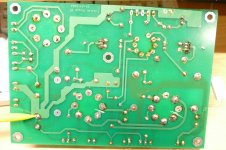
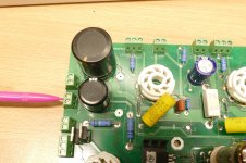
The actual star ground that all associated circuitry shall be connected to is the negative end of C2 where the yellow pencil points in picture #816. The left most thick trace that goes upward to C1 before turning left to the T1-RED-YEL connector is where the center tap on the HV winding of the power transformer meets the star (red pencil picture #818).
The middle trace that runs up to the front (top) of the board goes to the input connector and provides the ground for the preamp section.
The trace that branches off to the right at the middle of the board provides the ground connection for the power amp section. Both cathode resistors and their bypass caps are connected to it on the top side of the board.
If you are mounting the board in a metal chassis where the input connectors are electrically connected to the chassis (all metal RCA jacks mounted in the back panel) the preferred method of grounding the chassis is through the shields of the input cable that runs from the board to the jacks. Connect the shield from each cable to the input connector on the board AND connect the shield from the cable to the ground ring on the jack. The ground pin on the power cable or IEC connector should be connected to the spare hole in the T1-RED-YEL connector on the board.
If your housing is wood or some other non conductive material but a metal top plate is used, that plate MUST be connected to the T1-RED-YEL connector. The ground pin on the power cable or IEC connector must also be connected to the T1-RED-YEL connector.
Ideally there should be only one connection from circuit board ground to the chassis metal. Two or more connections may result in a ground loop raising the hum level. This may only be audible in setups that use high efficiency speakers.
Note that the board in the picture is the first SSE ever made in 2006. It has been used for experiments ever since and still works. It was never mounted. Some minor changes were implemented in 2012 to make life easier on the rectifier tube.
Attachments
Thank you. I should have mentioned that I built the circuit on a turret board with some point to point wiring also.
But I think your explanation told me what I need to know.
Thanks again
But I think your explanation told me what I need to know.
Thanks again