I have been trying to find a way to model a offset driver transmission line with coupling chamber but without success.
I can do the offset driver TL but don't see a way to add a coupling chamber.
Something like this T+A speaker:

I can do the offset driver TL but don't see a way to add a coupling chamber.
Something like this T+A speaker:
If you want to simulate custom configurations (arbitrary placement of chambers and stubs), how using about Akabak3 LEM (built in primitives) for modeling? Hornresp can export Akabak2 models for it's supported configs. Akabak3 student can be downloaded for free, but it requires Windows.
If you provide some rough dimensions and the driver spec, I'll provide you with an Akabak3 LEM example.
If you provide some rough dimensions and the driver spec, I'll provide you with an Akabak3 LEM example.
If you provide some rough dimensions and the driver spec, I'll provide you with an Akabak3 LEM exa
I am looking at the Peerless NE225W
300cm2 Constant diameter TL, 275cm line length of which maybe 55cm is coupling chamber or a stub after the port so effective line length is about 220.
My end goal is one large enclosure with 4 transmission lines. Maybe slightly differently tuned TL's can cover each other's frequency dips. It will be the bass section for a 3 way Omnidirectional loudspeaker.
End goal is a descendant of that Hegeman thing...which was (I think?) in SB years ago and there's some (Canadian?) company still making them. Anybody else remember that? I lost that hard drive stash but I recall all the thinking was in there. No reason not to reinvent the updated wheel, though, if it's fun/interesting.
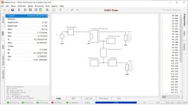
@ErikNils , I used the driver parameters as you listed. They look like a capture from a driver database, but there are differences to the actual datasheet (Le is different). I also used the physical sizes you specified and guessed at some other values based on the drawing in post #2. This is just a capture to show how it would be represented in LEM. The pressures shown are nearfield, and some tuning is still required 😉
Attachments
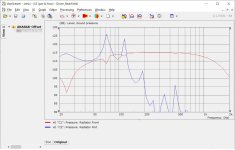

I also used the physical sizes you specified and guessed at some other values based on the drawing in post #2.
Hi Don,
Just out of interest, what dimensions did you use for the port tube? The only way I can get close to your AKABAK results is by making it 55 cm long, the same length as the stub.
Kind regards,
David
The transmission line and chambers are all 20x15cm rectangle cross sections (300cm^2).
The lengths used are :
OffsetChamber : 20cm
TransmissionLine : 200cm
ExitChamber : 30cm
PortTube : ellipse (20x10cm) x 15cm long
The lengths used are :
OffsetChamber : 20cm
TransmissionLine : 200cm
ExitChamber : 30cm
PortTube : ellipse (20x10cm) x 15cm long
- Home
- Loudspeakers
- Multi-Way
- Offset driver TL with coupling chamber in Hornresp