Everyone says that TV damper diodes can take a heavy beating. I want to find out how realistic the maximum current data are when used for HV rectification. I have a few EY80s I'm willing to sacrifice. Datasheet says max current 180 mA AND 'peak' current 400 mA. That's for their intended use in TVs, but how does that translate to rectification duties?
Main question: what will happen when they fail? Red (orange, yellow) plating I guess, and then? They just stop working? Or a short between anode and cathode?
Main question: what will happen when they fail? Red (orange, yellow) plating I guess, and then? They just stop working? Or a short between anode and cathode?
How are you intending to monitor them?
And how will you load them?
You will probably need to soak test with different loads - could be years before you have a worthwhile conclusion.
Would be interesting how many kilowatt/hours are needed 😎
And how will you load them?
You will probably need to soak test with different loads - could be years before you have a worthwhile conclusion.
Would be interesting how many kilowatt/hours are needed 😎
Stick 'em in a typical cap input rectifier circuit with a 'reasonable' load (80mA say), then start increasing the capacitance. Eventually you should get blue flashes in the tube. The capacitance limit (for a given source resistance) is probably the most useful single-figure metric for characterising a tube recto, at least for our typical audio applications. A bunch of other stuff can be inferred from it.
Don't hot-switch them, since that will skew the death rate!
Don't hot-switch them, since that will skew the death rate!
Last edited:
I remember that in our B/W TV they usually failed with a blue-ish glow, gone gassy, regularly after 2 or 3 years of service. The tube could no longer stand the reverse kV from the flyback transformer.
In my 1st attempt to use one in diy rectifier service 15 years ago it had to work into a 150uF 400V cap with what was supposed to be a 100 ohm wire wound series resistor. However I had actually fitted a 10 ohm carbon film. On an accidental mains power cycle the inrush current into the depleted cap, the cathode still hot and conducting like mad, the resistor exploded with a loud bang sending shrapnel around, the poor PY88 flashed over and lost pieces of it's cathode material, which ended up loose inside the glass.
The tube however survived and is still doing its job, now behind a 200 ohm wire wound ...
Last edited:

I was not expecting that M Night Shayamalan ending!The tube however survived and is still doing its job
I should have mentioned that the power cycling event in post #6 was during breadboarding and presumeably only happened so violently because the rectifier was directly plugged into my 500VA lab isolation transformer which has a 7 ohm secondary rated 2A / 240V. So the instantaneous inrush current could have well been on the order of 10A.
A more practical 250mA transformer winding usually has more than 10x the DCR !
A more practical 250mA transformer winding usually has more than 10x the DCR !
I haven't seen damper diode datasheets that mention a capacitance limit, that's pretty much what brought up this experiment.The capacitance limit (for a given source resistance) is probably the most useful single-figure metric for characterising a tube recto, at least for our typical audio applications.
The 150 µF Sorento used seems like a lot, much more than the usual max 50 or 60 µF for dual diodes. So far I've ran my EY80 into 75 µF for a year or so without problems.
And this is why I pay the weight penalty to do choke input filters.
The data sheets spent their space showing the limits for their intended usage. It is unfortunate that they did not design for service as rectifiers, as I suspect the voltage drop could be reduced by a fair bit. The high PIV requirements, and their use as literally dampers required emphasis on other performance metrics.
Even the big ones like 6CJ3 with 2.5-ish amp heaters drop more voltage than a GZ34...but the GZ34 will get quite upset with damper service. That would be a 5A/6.3V tube...in double diode rectifier config. Nobody turned loose one of those.
Douglas
Yes, it would be very interesting to see some damper diode sacrificed at the altar of capacitance!I haven't seen damper diode datasheets that mention a capacitance limit, that's pretty much what brought up this experiment.
If you do, be sure to give us all the juicy details:
Transformer primary resistance;
Transformer secondary resistances;
Primary no-load voltage;
Primary no-load voltage;
Secondary no-load voltage;
Load resistance;
Capacitance at which it blew!
Load resistance;
Capacitance at which it blew!
Last edited:
Thanks Merlin, will do. They only cost a few €.
I was setting up, I have a custom power transformer for a preamp I'll build, with a separate 6,3V winding specifically for two EY80s (1,8A)
One EY80 connected: heater voltage drops to 5,3 V. Second one connected: 4,3V.
Let's just say I'm not happy.. (No other secondaries were connected)
I was setting up, I have a custom power transformer for a preamp I'll build, with a separate 6,3V winding specifically for two EY80s (1,8A)
One EY80 connected: heater voltage drops to 5,3 V. Second one connected: 4,3V.
Let's just say I'm not happy.. (No other secondaries were connected)
Not so easy, I just did the following experiment:Yes, it would be very interesting to see some damper diode sacrificed at the altar of capacitance!
A pair of brand new 22 cent NOS EY88 in a hybrid bridge with 1N5408.
2 isolation transformers 65VA 230 / 230V in parallel, 130VA total.
Combined primary DCR 15 Ohm.
Combined secondary DCR 22 Ohm.
AC secondary no load 265V RMS.
Straight into 2 x1000uF in series, so 500uF effective.
No series resistors aside from transformer DCR.
Various incandescent light bulbs as load.
No precondioning, no power sequencing, just switch on, heaters and hv together.
Watching lamps coming to life gradually, and stay on.
No problem whatsoever ...
DC load current with 2x25W/230V in series 86mA and 315V.
DC load current with 2x40W/230V in series 141mA and 300V.
DC load current with 2x60W/230V in series 210mA and 289V.
Next could be to connect the 2 transformers in series and repeat with twice the voltage ... or connect tubes as doublers ...
Interesting! A hybrid bridge does mean only half the reverse voltage across the tubes though, making it less stressful compared to a two-diode arrangement.
Well, aren't dampers particularly good in withstanding reverse voltage stress ?
But the test setup can be easily reconfigured to either a CT full wave or a doubler.
Maybe a doubler should be next ...
But the test setup can be easily reconfigured to either a CT full wave or a doubler.
Maybe a doubler should be next ...
Perhaps just do a low voltage dc supply through the DUT diode. For common vacuum diodes I've used 24Vdc, 36Vdc and 48Vdc (comprising 12V 7Ah PbAc monoblocks) to measure the on-current through a diode, and also observe if the current falls off over a short period. For a 5U4/5AS4, that sometimes reaches 300mA or a titch over at 48Vdc. If you have 5 available batteries, or a lab power supply with say a 1A capability, then could be an easier way to both check the performance of the diodes you are wanting to test, and give a stress setup for watching how on-current could demise over time.
Remember that for cap input rectifier use, the diode current is a shortish duty-cycle half-sine pulse, where the peak current achieved depends on the health of the diode.
Remember that for cap input rectifier use, the diode current is a shortish duty-cycle half-sine pulse, where the peak current achieved depends on the health of the diode.
Well, aren't dampers particularly good in withstanding reverse voltage stress ?
But the whole point of this thread is to try to find the pracical limit of use, in an application they were never specified for, but which we would like to use them in, ie. as a standard cap input two-phase recto. We don't need to consider conservative use cases, they go without sayingPerhaps just do a low voltage dc supply through the DUT diode.
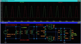
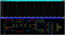
Here's the sim for my test setup.
The emphasis is on tube peak current here.
500uF case: just short of 900mA peak (DS max for PY88 is 500mA)
50uF case: almost the same.
5uF case: 600mA.
The emphasis is on tube peak current here.
500uF case: just short of 900mA peak (DS max for PY88 is 500mA)
50uF case: almost the same.
5uF case: 600mA.
Attachments
The demise of a DUT diode could be via a few paths I'd anticipate. Perhaps hot turn-on tests would be skewed by damage to the cathode at point locations where a large peak current was concentrated in a small cathode region prior to the entire cathode attaining a more uniform operating temperature. The datasheet current level limits for common rectifier tubes typically give a much higher peak current level than for continuous duty.
The demise of a DUT diode from continuous duty is perhaps a little more complicated as to what may eventually cause demise, as well as the demise may exhibit different characteristics - so a lot more experimental data may be needed to give credible insight into what could happen generally for anyone with a damper tube. Sure, if the demise is catastrophic then that may highlight the form of demise (eg. internal arcing from PIV due to internal gas build-up from outgassing or debris coming off the cathode). I guess this is the vagueness I see with the start of this test campaign. Another viewpoint is that if a test diode fails at certain test conditions then how does one ascribe a 'safe' operating condition unless it is done via statistical tests, or is the intent just to use 'wing-it' margins.
From a typical diode datasheet, the on-voltage versus conduction current plot generally stops at some level that may go to the peak continuous current value, but doesn't show what happens for higher peak current levels as they extend to the hot turn-on damage level. Text books will show that the nice V-I curve will soon become non-linear and roll-off the peak current that can be forced through the diode, and it is likely that roll-off characteristic is one form of demise, as well as one form of insight as to what the diode current capability is for an application like in a rectifier with capacitor input filtering.
- Home
- Amplifiers
- Tubes / Valves
- Vacuum tube diode destructive test