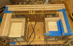
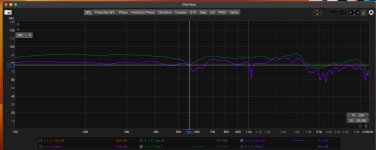
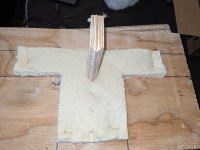
This is my first attempt at speaker design from scratch (repurposing old BOSE acoustimass drivers). Bringing them together in a TMT arrangement with the satellite FR drivers. Attached is the box design. Attached also are some 1'/15ms gated measurements using a umm-6. Before and after felting the inside (Felt from a vintage westinghouse cabinet). I am seeing some sort of interference at just about 550Hz that the felting did not take care of.
What sort of obvious thing am i missing? (other than that these drivers are way outside of their intended usage?
What sort of obvious thing am i missing? (other than that these drivers are way outside of their intended usage?
Attachments
The gate was located on the back wall earlier on, and the port ended up being too long....but like an idiot I didn't keep those files....
Thanks for the suggestion! will give it a shot tonight.
Thanks for the suggestion! will give it a shot tonight.
Hi @AllenB .
Looking at your response again, I may have misread it completely.
The response is from about a foot away, with a 15ms gate on the signal. (I based this on the impulse decay). the dip stays even when dropped to 5ms, so definitely from the box.
What I misread you suggesting was the movement of the entrance to the port, which I messed with a bunch. I went so far as to fabricate a center "block", to eliminate reflections across the long dimension. The dip persists!
The thickness of the cabinet front to back is 6.5". Could this be a 1/4 wave resonance of some sort? Or is there something fundamental that I am missing wrt the driver (which was designed to be used with effectively no crossover being managed by the ports in the woofer).
Right now, I am using a repurposed felt for the walls. Would eggcrate have any meaningful effect on things?
Attachments
Yes, I was talking about setting the measurement gate small then sliding it open and watching whether 550Hz starts out normal then dips afterward. All this done after the measurement has been taken.
Ok, as for the cabinet you'll want to look for paths from the driver to somewhere it reflects, then back again which are a total of half a wavelength at 550Hz (about 1 foot).
BTW, egg crate foam is not very effective.
Ok, as for the cabinet you'll want to look for paths from the driver to somewhere it reflects, then back again which are a total of half a wavelength at 550Hz (about 1 foot).
BTW, egg crate foam is not very effective.

…while it does a remarkably better job than felt. The real acoustic egg crate stuff is very effective from about 400-500Hz up to very high frequencies, because of the egg crate profile.BTW, egg crate foam is not very effective.
Sadly most of us need stuff that is effective in midrange territory. Dense mineral wool, acoustic products like cotton fiber and melamine or polyester foams are preferred.
I would take true nearfield measurements of the woofer and port and see if that sheds any light on what's going on. For this you should be about 1/4 inch away from the speaker cone for one measurement.
Then do another measurement with the microphone centered over and flush with the port opening.
You don't want the SPL at the microphone to be much over 110 dB, so don't get crazy with the volume.
Then do another measurement with the microphone centered over and flush with the port opening.
You don't want the SPL at the microphone to be much over 110 dB, so don't get crazy with the volume.
HI @mattstat ! Well, i didn't see this until after I ripped everything apart! I had just thrown in the towel on this design, thinking the symmetry of everything was a doomed starting point. Let me get out the drill, and follow up on this before I head into revision zone..."Luckily" I got sucked into some auto repair, which kept the saw at bay...
It's also worth noting that at 500 Hz, you tend to need significant thickness to absorb completely. If it is a simple standing wave issue in your enclosure you probably need more material than you have in the image, and you may need it on more than one wall (I'm unsure how much you had in there). But felt is also a bit of a wildcard, since some products are down around 0.2 NRC at 500 Hz and others are close to 1. There are lots of different types of felt.
A few examples of other materials at different thicknesses:
https://www.soundassured.com/blogs/blog/how-thickness-of-acoustic-foam-panels-affects-absorption

https://www.buyinsulationproductstore.com/owens-corning-703-fiberglass-acoustic-board-2-3/

A few examples of other materials at different thicknesses:
https://www.soundassured.com/blogs/blog/how-thickness-of-acoustic-foam-panels-affects-absorption
https://www.buyinsulationproductstore.com/owens-corning-703-fiberglass-acoustic-board-2-3/
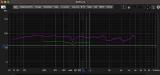
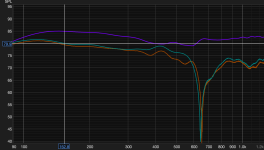
Thanks @mattstat for the suggestion. Interesting results, indeed. The following seems to indicate that the ports themselves have some serious issues...but it is interesting that the frequency is off ~100Hz from the combined measurement.
Attached is very nearfield (~4 cm) measurements, gated at 15 MS. The volume was adjusted between runs, so ignore the SPL magnitude.
Purple is the woofer, orange/green are port1 port two.
and a measurement made about 24" out.
Why would the dips be locate about 100Hz off.
Is part of this because the ports are too close (~7" CTC) to the woofer, and I am seeing interference due to an unfortunate distance between the back of the woofer and the port exit?
Thanks for any input, folks!
Attachments

As long as out of phase energy isn't directly leaking out through the port, being too close to the woofer shouldn't have a major impact. There are plenty of small speakers that use ports quite close to woofers.
Without being there and seeing exactly what you're doing, it's hard to know for sure what things are showing up in your measurements. 4 cm is actually not nearfield in the sense that we're using it here.
The article below talks about these topics and is worth reading. It's pretty short but covers a good amount of ground. Excerpt here is just the most relevant one related to distance.
https://audioxpress.com/article/measuring-loudspeaker-low-frequency-response
"For the near-field technique to work properly, the microphone should be placed as near to the center of the diaphragm as possible. Keele shows that a microphone distance less than 0.11 times the diaphragm effective radius results in measurement errors of less than 1 dB. As an example, a 6.5" driver will typically have an effective cone diameter of 5" or an effective radius of 2.5". For this driver, the microphone should be placed within 0.275" of the driver dust cap."
- Home
- Loudspeakers
- Multi-Way
- Why the dip at ~550Hz (nearfield)