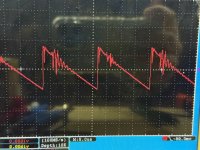
Hi. I'm working on the power supply for this Korean amplifier, no brand, but the board is from Zenon, the old 7kw version, manufactured in 2008.Is it normal for the power supply PWM to have these "artifacts"?
thanks


thanks
If you ground the scope probe (using the short ground lead that connects to the end of the probe) to the source leg of the FET you're checking the gate leg, does the waveform change?
The glitch on the falling side is normal but the rising side of that waveform is a mess.
Are all of the FETs in the circuit?
What are the FETs?
Gate resistor values?
Set the scope to 10us and 5v/div and DC coupling.
The glitch on the falling side is normal but the rising side of that waveform is a mess.
Are all of the FETs in the circuit?
What are the FETs?
Gate resistor values?
Set the scope to 10us and 5v/div and DC coupling.
yes, the waveform is the same by connecting the ground to one side of the transistor. yes, all the fets are on the board. it has 36 IRFP1405, 22 ohm resistors. i have seen that pin 5 of the tl494, in the triangular wave, also has artifacts… i have changed the tl494 to rule it out, but it persists… the pwm in the output part is perfect, square wave without artifacts, so i rule out any problem in the oscilloscope or the measurement probe.
Last edited:
What does the scope (or any meter) give as the duty cycle?
Is the amp drawing excess idle current?
Are the FETs heating up excessively?
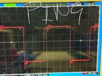
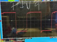
Post a waveform directly from pin 9 or 10 of the 494.
For the oscillator, ground the clip for the probe on pin 7 of the 494. Does that clean it up?
Is the amp drawing excess idle current?
Are the FETs heating up excessively?
Post a waveform directly from pin 9 or 10 of the 494.
For the oscillator, ground the clip for the probe on pin 7 of the 494. Does that clean it up?
I have removed the rectifier diodes to work on this more safely. Without the rectifier diodes it consumes 4.5A and nothing gets too hot. I am publishing 2 images with the waveform on pins 9 and 10. Using pin 7 as ground, everything is the same.
Attachments

Are you saying that the oscillator waveform is no cleaner with the short ground clip connected directly to pin 7 (not to any other ground point) of the 494?
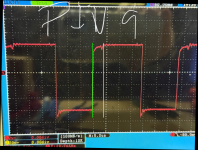
Sorry, I made a mistake when connecting the probe ground to another pin. By connecting to pin 7, the waveform on pins 9 and 10 is much cleaner.

That should be causing an excessive idle current and FET heating. The waveform between the green and yellow lines appears to be wrong.
The rise at the green line shouldn't be happening until the point at the yellow line.
How long before the PS FETs get too hot to hold?
Multimeter set to DCV, black probe on pin 7, DCV on pins 3 and 4?
The rise at the green line shouldn't be happening until the point at the yellow line.
How long before the PS FETs get too hot to hold?
Multimeter set to DCV, black probe on pin 7, DCV on pins 3 and 4?
Attachments
They do not exceed 35 celcius for more than 15 minutes on.
the voltage on pin 3 is 0.029vdc and on pin 4 0.054vdc. taking pin 7 ground as reference.
the voltage on pin 3 is 0.029vdc and on pin 4 0.054vdc. taking pin 7 ground as reference.
Not on the waveforms you posted. It looks more like 55%.
Do you have another amplifier that you can check the drive on to see if the scope produces similar waveforms?
Do you have another amplifier that you can check the drive on to see if the scope produces similar waveforms?
I rule out any problem with the oscilloscope, since it has been checked and does not give any errors. I have removed the IRFP1405 from the board and the PWM waveform is almost perfectly square. Do you think the driver transistors (A1715/C2814) are causing this? Can I replace them with BD139/140 to drive the 36 IRFP1405?
I know this... You cannot have more than a 50% duty cycle with a push-pull supply and not have shoot-through (cross-conduction) which causes excessive current draw. That's simply not possible.
What if you install only one FET per bank for one transformer? If the transformer secondaries are in series, this would have to be for the transformer with the grounded secondary center tap.
Are you sure that those are the correct driver part numbers?
What if you install only one FET per bank for one transformer? If the transformer secondaries are in series, this would have to be for the transformer with the grounded secondary center tap.
Are you sure that those are the correct driver part numbers?
- Home
- General Interest
- Car Audio
- PWM power supply on zenon 7kw board