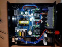
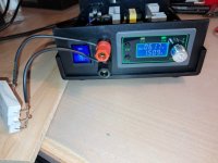
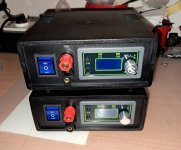
I made a couple of cheap Bench PS myself from components from Aliexpress. Total price is around 60-70eur for both. I often need a single or dual PS for testing various DIY devices. The concept is an AC/DC fixed power supply 48V 4A, then a noise filter 50V 4A, then an adjustable DC/DC step down power supply (with a current limit) of 50V 5A and again a noise filter 50V 4A. The devices are not grounded to IEC, so I could make dual power supplies up to +-45V. Realistic possibilities are approximately 45V and 3A. Plastic box - 160x160x65mm.
Links:
https://www.aliexpress.com/item/4000287613667.html
https://www.aliexpress.com/item/1005005396072901.html
https://www.aliexpress.com/item/1005007948946980.html
https://www.aliexpress.com/item/4001224998003.html
https://www.aliexpress.com/item/1005003597145707.html
Links:
https://www.aliexpress.com/item/4000287613667.html
https://www.aliexpress.com/item/1005005396072901.html
https://www.aliexpress.com/item/1005007948946980.html
https://www.aliexpress.com/item/4001224998003.html
https://www.aliexpress.com/item/1005003597145707.html
Attachments


Nice project, and nice build! I have been amazed at how switching/buck technology and a huge selection, combined with ultra inexpensive volume manufacturing has made such projects simple to "build with a screwdriver" with amazing capabilities (compared to 10 pounds of transformers and heat sinks) for pennies on the dollar. I have been thinking about getting one of those adjustable output regulators, so I'm interested in hearing future updates as to how well it is working for you, now much ripple, how noisy it is in adjacent radios and audio circuitry, thermal capability, etc.
It looks like it will be quite useful. If it were mine, I would probably do some testing at moderate loads (that you might use) over a couple of hours at least checking for any thermal issues. I would not expect to get the full output rating without better ventilation. Worst case scenario a small fan might be needed, but these boards are so efficient that for more reasonable loads it may be just fine.
I was curious that the filter boards do not indicate what capacitance and voltage rating the capacitors have- If the filter is rated at 50V it may have 50V capacitors, which is not much headroom for a constant 48V input, but again may not be a problem if they were manufactured well. If the capacitance value is rather small, you may want to add a higher value cap at the final output banana posts to give the supply a better output transient response and lower output impedance if you are going to use loads with a lot of dynamic variation, like audio circuits or motors. A bleeder resistor at the output may be good if you notice the output voltage stays high even after power-off, especially if you add a larger output cap.
A fuse inline with the output may also be warranted- It sounds like the output voltage regulator has some pretty good protections (current limiting, auto shut off, etc) so this may not be necessary. At some point however, you will end up shorting the output (kind of inevitable) and it might be good to do it as a test to see how good the protection is rather than possibly losing it in the heat of battle and being down a supply mid-experiment.
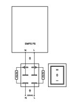
What are the power resistors for at the power switch?
Anyway, Good on you, major kudos, and very enjoyable to hear about, and nice to see your photos. Please give updates . . . and Thank you.
It looks like it will be quite useful. If it were mine, I would probably do some testing at moderate loads (that you might use) over a couple of hours at least checking for any thermal issues. I would not expect to get the full output rating without better ventilation. Worst case scenario a small fan might be needed, but these boards are so efficient that for more reasonable loads it may be just fine.
I was curious that the filter boards do not indicate what capacitance and voltage rating the capacitors have- If the filter is rated at 50V it may have 50V capacitors, which is not much headroom for a constant 48V input, but again may not be a problem if they were manufactured well. If the capacitance value is rather small, you may want to add a higher value cap at the final output banana posts to give the supply a better output transient response and lower output impedance if you are going to use loads with a lot of dynamic variation, like audio circuits or motors. A bleeder resistor at the output may be good if you notice the output voltage stays high even after power-off, especially if you add a larger output cap.
A fuse inline with the output may also be warranted- It sounds like the output voltage regulator has some pretty good protections (current limiting, auto shut off, etc) so this may not be necessary. At some point however, you will end up shorting the output (kind of inevitable) and it might be good to do it as a test to see how good the protection is rather than possibly losing it in the heat of battle and being down a supply mid-experiment.
What are the power resistors for at the power switch?
Anyway, Good on you, major kudos, and very enjoyable to hear about, and nice to see your photos. Please give updates . . . and Thank you.
Very cool project. Personally I 'd probably add a small fan. Finding out how noisy the output is would be interesting too.
Great! Have you had a chance to check remaining ripple yet. Btw I
recently ordered the same filters.
recently ordered the same filters.
Thanks everyone, it's an interesting little project, like LEGO.😁
I was able to buy a couple of off-the-shelf Bench PS, there are some really nice ones out there. A much higher price is not a problem for me, but realistically my needs are modest, and it is more interesting to make one. I don't even know how reliable this is, I don't have strong enough resistors to test it. It's almost a 200W power supply though. I certainly won't bully it too much.
As far as measurements are concerned, I will measure the effect of these filters, I have an oscilloscope.
The capacitors in the filter are 50VDC, maybe they should be replaced with some LOW ESR of 63/80/100V if used frequently and with higher loads. But the quality of the other capacitors is probably not much better either, and for SMPS they must be of the highest quality possible.
Two wire resistors 47 ohms 5W are used for inrush current limiting to save the switch. It happened to me that the contacts of the switch combined with the SMPS power supplies were welded. This AC/DC power supply has some NTC resistor between the diode bridge and the first capacitor, but its value is quite small, around 6 ohms. At the moment of switching on, the capacitor is empty and the starting current probably reaches several tens of amperes. In this way, I briefly turn on the switch in position 1, the resistors limit the current while the capacitor fills up, and after a few seconds I switch to position 2, which is a direct connection to the network.
Last edited: