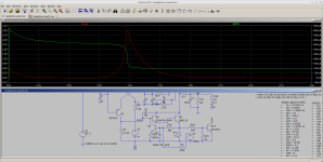
The JLH-like amplifier I designed/built has a nasty turn-on transient. That was an oversight on my part, I didn't simulate that. The problem is caused by the autobias circuit, which requires a ~100uF capacitor to charge to about Vbe before it begins to work. In the meantime the idle current and output voltage go nuts -- see below:

If the low pass filter capacitors are increased to, say, 500uF the problem is even worse.
The schematic above has my solution (the top half of the amp components are R23, R24 and Q13). It is a current-sensing transistor that turns on when the idle current is too high. The circuit can't completely eliminate the turn-on transient because at some point it could be triggered when playing at higher (but headphone-safe) volume. R23 is set to 1 ohm to illustrate the "nasty" turn-on transient.
When R23 and the corresponding resistor on the negative side are increased to 5K the transient looks like this:

Much better. The transient will still produce a fairly loud "thump" but nowhere near the 300mW max for your typical headphones.
The added circuitry doesn't increase the THD -- it simulates out at .006% for a 1KHz 4.5Vpp signal into 48 ohms, so the limiting circuitry isn't activated by normal-to-loud musical material.
If the low pass filter capacitors are increased to, say, 500uF the problem is even worse.
The schematic above has my solution (the top half of the amp components are R23, R24 and Q13). It is a current-sensing transistor that turns on when the idle current is too high. The circuit can't completely eliminate the turn-on transient because at some point it could be triggered when playing at higher (but headphone-safe) volume. R23 is set to 1 ohm to illustrate the "nasty" turn-on transient.
When R23 and the corresponding resistor on the negative side are increased to 5K the transient looks like this:
Much better. The transient will still produce a fairly loud "thump" but nowhere near the 300mW max for your typical headphones.
The added circuitry doesn't increase the THD -- it simulates out at .006% for a 1KHz 4.5Vpp signal into 48 ohms, so the limiting circuitry isn't activated by normal-to-loud musical material.
Attachments
I can't answer this how you would like, but a protection circuit normally achieves this, and protects you from DC. I have 3 relays in my signal path, and it's an upper tier brand. A phono center pin is probably just as bad as a sprung relay contact. Silver Nickel should be okay for headphones. If you use a DT relay, then the amp can see some resistors before flicking over to the headphones. So your spike has somewhere to go
My purpose was meant to highlight the design defect in a particular (and relatively popular) amplifier. Indeed, I first considered a relay based approach but, either way, at this point it would mean doing more "stuff" to address the problem. I elected to show an approach that (perhaps) is a bit simpler than a relay plus the ancillary circuitry needed to detect a DC fault. You'd need a window detector -- two comparators -- plus two low-pass filters -- plus a relay driver -- plus a relay. Vs. two transistors and four resistors per channel. I elected to take the simpler approach.
There is yet another reason to limit the peak idle current. With NO limiting, the peak current could get the output transistors dangerously close to their maximum SOA. Fast transistors also will FAIL very quickly when their SOA is exceeded. I know this: I've seen (and analyzed) failures due to it. The interesting failure signature of bipolar transistors that have been pushed beyond their SOA is that the typical failure location is on the tip of one of the emitter fingers -- the failure site usually is in the center of the die (that's where the transistor gets the hottest) -- and is a single melted spot where the current eventually concentrated to the point where the local power dissipation actually melted the silicon. BJT Finis.....
There is yet another reason to limit the peak idle current. With NO limiting, the peak current could get the output transistors dangerously close to their maximum SOA. Fast transistors also will FAIL very quickly when their SOA is exceeded. I know this: I've seen (and analyzed) failures due to it. The interesting failure signature of bipolar transistors that have been pushed beyond their SOA is that the typical failure location is on the tip of one of the emitter fingers -- the failure site usually is in the center of the die (that's where the transistor gets the hottest) -- and is a single melted spot where the current eventually concentrated to the point where the local power dissipation actually melted the silicon. BJT Finis.....

Weird complicated circuit. Normal Diamond will just auto bias.
Is the input coupled ? looks like it will gladly pass whatever DC it sees regardless.
Easier solution is turn it on and wait, then plug the headphones in.
Easier circuit without some strange auto bias that does not nail the transistors is feasible too.
Is the input coupled ? looks like it will gladly pass whatever DC it sees regardless.
Easier solution is turn it on and wait, then plug the headphones in.
Easier circuit without some strange auto bias that does not nail the transistors is feasible too.
OK...
What part is weird? The main current-sensing/feedback scheme is vintage JLH. I certainly do admit to some circuit mods to increase the original's open-loop gain -- the original version's input transistors' emitters are connected to resistors that in turn connect to the main Vcc/Vee, so there are some very strong limits on how low they can go to increase the inputs' Gm .... w/o greatly increasing the quiescent current in the transistors. I'm using some lower-voltage +/- Vref's to address that. By a factor of a bit more than 10. I thought that was a relatively conservative variation. That change also greatly improves the amp's PSRR.
I also am wondering how will 'normal diamond auto-bias', in the context of an all-BJT output pair, work? I know the usual Vbe multiplier can be employed in many situations: but that's not how the originator did it. Given the use of a PNP output on the positive side and an NPN on the negative side, frankly I don't know where a Vbe multiplier would work w/o some significant changes or additions to the original design. And in any event it wouldn't qualify as auto-bias. It's a thermal feedback loop, not current-based.
Diamond only needs additional drops for Darlington
In a opamp feedback loop distortion can be rather good and no DC offset issues.
I didnt mean to sound disrespectful, I can see the fun in the circuit.
But much easier ways to do it.
Circuit is already done and built, easy solution is let it stabilize first. I agree relay would help, but seems like to much work.
How much gain is used for the amp to have good level for various sources
Well for headphones it's totally adequate in terms of gain, no problem there. I'm having fun with it so it's all good 🙂. Just got done listening to Bruce Cockburn's "Dark Horse " album with it driving the headphones. Some nice stuff there.
I'm just a bit unhappy that the HA doesn't behave all that well during power-up but after that it's fine. One of those little make-it-better-yet things I guess
Thanks for the comments!
I'm just a bit unhappy that the HA doesn't behave all that well during power-up but after that it's fine. One of those little make-it-better-yet things I guess
Thanks for the comments!
They present a pretty good stereo image in some of those recordings the way the mix is done with the string instruments.
Its not a lot of reverb or overdone. Just up close and natural. Hard to describe.
Its not a lot of reverb or overdone. Just up close and natural. Hard to describe.
"Auto Bias"
T1 thru T4 thermally linked T5 and T6 outside the thermal loop.
No extra diode drops or VBE needed

T1 thru T4 thermally linked T5 and T6 outside the thermal loop.
No extra diode drops or VBE needed
Last edited:
- Home
- Design & Build
- Electronic Design
- JLH amplifier turn-on transient and a way to mitigate it.