Hi all, I've build that amp following Mark's excellent video series, and even though I remember Mark saying it was dead quite I have some slight audible 100hz hum out of the speakers (European 50hz mains).
Its about 8mV peak2peak measured at speaker terminals.
The PS for this SE KT88 amp is designed around 380-0-380V, 200mA PT, 5ar4 rectifier and CLC/pi filter for B+ (C1=10uF, L=10H, C2=200uF), and the output transformers are SE 5000k/8R (25:1).
Is my math right that:
1) the first cap should give 100v p2p ripple (assuming full wave rect., 50hz mains and 200mA of current: Vrpp = I/2fC)
2) the LC should smooth the ripple to ~125mV p2p (Vrpp = (Xc/Xl) * Vac(in) with Vac(in) being the p2p ripple V from point 1)
3) the 25:1 OPT should give ~5mV of final ripple at the speaker terminals?
If so, it seems that increasing C1 closer to capacitive max load of 5ar4 (60uF) would be the simplest choice if I wanted less hum. Are there any negative consequences of increasing C1 apart from getting a bit higher current from PT and B+?
With 20uF of C1 I have 79mA and 377V Anode to Cathode at Kt88 so still below 30W and the ripple at speaker terminals halfed as expected...
many thanks
Hello jank9:
I do not see a problem with increasing the value of C1.
As you indicate it being a 100hz hum I would be incline to make that change and also review the grounding network and look for a loop.
Do you have AC on the heaters? Did you reference it to ~ 25% B+.
Did you tie the output transformer to signal ground?
A schematic of actual build would be helpful as well. A photo or two of the completed layout also helps to see if there is a proximity interaction causing the hum.
Ideas to consider
I hope this helps.
Thanks SCD.
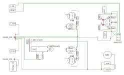
Attached is the amp schematic and the layout with grounding scheme (all groud connections in green). I have only one star ground connected to chasis, all other star grounds are not connected to chasis.
AC on the heaters is lifted from the ground with 2 x 100R.
I did my best to avoid ground loops but since this is my first point to ponit build all comments are appreciated.
thanks
Attachments

I would just tack an extra 30uf cap onto the first cap in the power supply and see if that helps your hum level. Quick, easy, and reversible.
Dan
Dan
If my math and formulas from the first post are right, adding extra capacitance in C1 definitely helps with the hum.. the only potential issues I see are:
thx
- rising inrush current drawn from PT at startup (I did some simulations in LTSpice and looks like inrush current jumps to 300mA+ with 30uf in C1 and my PT is up to 200mA)
- rising B+ and current - although here I have some space as my B+ is some 25V less than 460V from the schematics.
thx
You don’t show how you connected the HV center tap in your layout diagram. It needs to be directly connected the the ground side of the first cap.
It's there, it is connected to the ground wire going from 10uf and 200uf grounds to chassis ground.You don’t show how you connected the HV center tap in your layout diagram. It needs to be directly connected the the ground side of the first cap.
I guess what I am trying to understand is why the original design opted for C1=10uF which according to my math is bound to give 5mV ripple (where 1mV is probably the desired level) rather than lowering the PT ratio to say some 360-0-360 and rising the B+ to desired level with some higher C1 at the same time achieving lower ripple?I would just tack an extra 30uf cap onto the first cap in the power supply and see if that helps your hum level. Quick, easy, and reversible.
.... I remember Mark saying it was dead quite I have some slight audible 100hz hum out of the speakers (European 50hz mains).
Its about 8mV peak2peak measured at speaker terminals.
You've got to take ''dead quiet,'' always with a dose of scepticism. His ears are not your ears. His speakers are not your speakers. And everyone wants to say their final product is dead quiet.
Also, when you report a peak2peak signal, you should convert that to RMS voltage to make relative power comparison. Your output signal is 2.8mv. That's like hooking a low output phono cartridge across 8R instead of 47K and feeding it to a speaker directly.
DCE1198 has the fast answer. Caps and clip leads.
Last edited:

It matters where on that line it connects. Needs to be exactly at the ground side of the 10uF to localize the ripple current into that cap and keep it from affecting the rest of the ground system. I've worked on amps where the CT was connected to the ground system but by moving it about 3 inches to the first cap it made a measurable decrease in noise level at the speaker terminals.It's there, it is connected to the ground wire going from 10uf and 200uf grounds to chassis ground.
Not sure I follow. In the first post I did some calculations which - if they are right - lead me to belive that I actually should hear/measure such level of ripple given this specific design of PS filtering... if this is right, then I've identified the source of hum, haven't I?You've got to take ''dead quiet,'' always with a dose of scepticism. His ears are not your ears. His speakers are not your speakers. And everyone wants to say their final product is dead quiet.
Also, when you report a peak2peak signal, you should convert that to RMS voltage to make relative power comparison. Your output signal is 2.8mv. But you don't know the source. It could be microphonics from PT hum or other heater voltage leaks or loop noise. You should avoid sims for troubleshooting.
BTW, my intention behind this post was to confirm that the source of 100hz hum is in fact due to insufficient PS filtering so that I don't have to look for its sources by trial and error..
Last edited:
Not sure I follow. In the first post I did some calculations which - if they are right - lead me to belive that I actually should hear/measure such level of ripple given this specific design of PS filtering... if this is right, then I've identified the source of hum, haven't I?
Granted, the 100Hz is the primary clue, and that is why I edited my first hastily posted reply that didn't weight that high enough at first read. But you grabbed it before my edit hit the page, unfortunately. So, from your own deduction, it's probably going to be a simple fix. We all have to decide what our level of expectations is vs. our level of tolerance. Your initial calculation for 5mV of ripple vs. having only 2.8mV of measured ripple seems like a fortunate position to have. Keep us posted to the steps as you continue to work the ripple down to 1mV. It's too bad we can't hear what you hear.
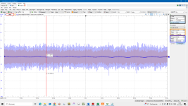
Thanks, Dan. This is what I did (went from 10uf to 30uF) and as predicted the hum measured at speaker terminals decreased from 8mV to 2mV pp (see attached). Hence my second question from the first post whether there is anything I should worry about when increasing C1 in CLC PS filter (apart from 5AR4 limit).Two clip leads, a cap, and you would have your answer.
I suspect there must be some trade-off when increasing C1, otherwise I find it hard to believe that such an elaborated design (judging by the number of revisions) settled with relatively poor PS filtering which should be key for SE (unless 5mV ripple is considered 'good enough' standard for SE)
With this thread I wanted more to explore some key considerations behind PS design rather than ways around my hum (because those I think I've identified)
Attachments

BTW, my intention behind this post was to confirm that the source of 100hz hum is in fact due to insufficient PS filtering so that I don't have to look for its sources by trial and error..
Are you hearing and measuring the ripple with the screen tap connection or under triode connection? Have you tried both and found any difference?
Here's a power supply that has been designed twice, once for 60hz mains and again for 50hz.

Please to notice the extra RC filter for 50hz.
Taken from an older page on 300b design by @Suncalc
w
Please to notice the extra RC filter for 50hz.
Taken from an older page on 300b design by @Suncalc
w
2mv is still on the high side IMHO even for AC heaters.
What does an FFT of the output show? I wouldn't use anything else to hunt down a hum or hiss issue.
What does an FFT of the output show? I wouldn't use anything else to hunt down a hum or hiss issue.
Chasing hum in p2p tube builds--especially SE--can be frustrating.
I know we're talking 100hz and not 50hz, but I'd still explore the low hanging fruit. Before messing with the circuit too much, I'd do as others advise above and post pics of the top and bottom of the chassis.
Additionally, you haven't mentioned the rest of your system. If you have something else where signal ground is connected directly to earth (including video or internet), that could be your loop. Sometimes that makes noise; sometimes it doesn't. You can try isolating signal from earth with a 10R or so resistor for testing purposes. If that works, you'd want to add some diodes going each way in parallel for safety and likely a little cap for rf.
Finally, be sure that the electrical hum is all that is irritating you. Edcor PTs (though not only Edcor PTs) often buzz a bit. If you are hearing combined noise, mechanical isolation may be improve your overall experience.
There are many threads on these things with embarrassing situations by some of us fighting bigger problems. 2mv isn't awful in the grand scheme and counts as "quiet" for many with less sensitive speakers, who sit farther from them, or both.
Paul
The ripple is smaller in triode mode 2,7mV versus 3,7mV in UL mode (both with C1=20uF in PS).Are you hearing and measuring the ripple with the screen tap connection or under triode connection? Have you tried both and found any difference?
- Home
- Amplifiers
- Tubes / Valves
- Kegger/blueglow KT88 PS hum