Hi all.
I am building a 8 ch DAC based on 4 TDA1387x8 boards. Each TDA1387x8 I/V stage is based on two NE5534 with a 1k feedback resistor (R4/R5) + 4.7nF cap (C3/C4). A 47pF cap connects pins COMP and COMP/BAL. It is basically 4 ProtoDACs with an active output stage.
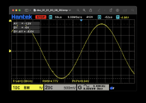
I am a computer engineer for 30+ years, but went down the software path. So electronics is not my strong... What I am trying to understand is why I always get aprox. -4.4VDC before the coupling caps (opamp output - pin 6) when there is nothing playing. If I put a 2kHz sinewave at 0db, I get aprox. 6.8V peak to peak (a little bit more than what I aimed for, need to adjust R4/R5) but the osciloscope shows that the minV is -8VDC and maxV is -1.2VDC. I.e., the signal is "centered" at -4.4VDC.
I built a single chip version (2ch only) in a perfboard and it plays just fine - after the MKP 4.7uF coupling caps (C13/C14), I get the sinewave from -3.4VDC to +3.4VDC as expected. Too early to say something about its sonic capabilities as I have just one channel pair done and the PSU built in a protoboard.
I've attached the schematics of one channel pair (1 TDA1387x8 + its I/V stage) and the oscilscope measurement.
Is it normal to have the signal "shifted" by -4.4VDC? Why?
Thanks!
I am building a 8 ch DAC based on 4 TDA1387x8 boards. Each TDA1387x8 I/V stage is based on two NE5534 with a 1k feedback resistor (R4/R5) + 4.7nF cap (C3/C4). A 47pF cap connects pins COMP and COMP/BAL. It is basically 4 ProtoDACs with an active output stage.
I am a computer engineer for 30+ years, but went down the software path. So electronics is not my strong... What I am trying to understand is why I always get aprox. -4.4VDC before the coupling caps (opamp output - pin 6) when there is nothing playing. If I put a 2kHz sinewave at 0db, I get aprox. 6.8V peak to peak (a little bit more than what I aimed for, need to adjust R4/R5) but the osciloscope shows that the minV is -8VDC and maxV is -1.2VDC. I.e., the signal is "centered" at -4.4VDC.
I built a single chip version (2ch only) in a perfboard and it plays just fine - after the MKP 4.7uF coupling caps (C13/C14), I get the sinewave from -3.4VDC to +3.4VDC as expected. Too early to say something about its sonic capabilities as I have just one channel pair done and the PSU built in a protoboard.
I've attached the schematics of one channel pair (1 TDA1387x8 + its I/V stage) and the oscilscope measurement.
Is it normal to have the signal "shifted" by -4.4VDC? Why?
Thanks!
Attachments
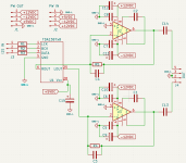

There is a output bias of the tda1387 for about 1.08mA when there is no signal. The signal is super imposed on it also 1mA . Your opamp stage is inverting so output after I/v is - ?V depending on your resistor value. So there is always a DC voltage. That is why you need C13/14 to filter the DC voltage out.
Last edited:
Thanks! That makes a lot of sense now.There is a output bias of the tda1387 for about 1.08mA when there is no signal. The signal is super imposed on it also 1mA . Your opamp stage is inverting so output after I/v is - ?V depending on your resistor value. So there is always a DC voltage. That is why you need C13/14 to filter the DC voltage out.
Didn't know about 1.08mA bias current - now I re-read the datasheet and found this info.
As there are 8 chips, with a 1k feedback resistor, I should be getting something near -8VDC instead of -4.5VDC (VDD is 5V). Is there anything else that I am missing here?
If that is the case and the output is supposed to be -8VDC, I will have to change the opamp power supply from +/- 12VDC to +/- 15VDC to acommodate a 6V peak to peak at 0db. No problem.
Thanks again!