Hi, i have some problems regarding stereo to mono coversion that i need for a HI-FI portable speaker.
I searched the internet a lot, but i couldn't find a consistent answer.
So, my question here is: what is the best possible way (circuit) to convert a stereo signal to a mono signal
My idea is to use a NON inverting Op-amp voltage summer with equal resistor values (I need the output to be in phase with the input).
But i dont know if this works perfectly.
Maybe there is no way to convert stereo to mono and a true mono signal can only be generated directly from a computer?
If there is a way to do it in the way i want, let me know.
Thanks in advance.
I searched the internet a lot, but i couldn't find a consistent answer.
So, my question here is: what is the best possible way (circuit) to convert a stereo signal to a mono signal
- Without causing any additional distortion
- Without causing artifacts
- Without causing amplitude drops / imbalances
My idea is to use a NON inverting Op-amp voltage summer with equal resistor values (I need the output to be in phase with the input).
But i dont know if this works perfectly.
Maybe there is no way to convert stereo to mono and a true mono signal can only be generated directly from a computer?
If there is a way to do it in the way i want, let me know.
Thanks in advance.
If you have a high impedance load, two resistors will do nicely.

Why does it say unbalanced mono? Does balanced mono exist and maybe its better?
Anyway, i wanted a solution with OpAmps because my load is pretty low impedance...
The OpAmps are powered with dual supply (±15V).
Anyway, i wanted a solution with OpAmps because my load is pretty low impedance...
The OpAmps are powered with dual supply (±15V).
Last edited:
I need the convertion to be as good as possible. So that the music sounds exactly the same down to tiny details.
It has to sound exactly the same as heard from a stereo system.
But all will be blended into a single signal.
No imbalances between left and right volumes, etc.
It has to sound exactly the same as heard from a stereo system.
But all will be blended into a single signal.
No imbalances between left and right volumes, etc.
I think i will use this configuration, but before that i need to know three last things:
- Can the output of the inverting summing OpAmp (virtual earth mixer) be connected to other OpAmp stages (like filters and gain stages) that share the same dual power supply without creating interactions / problems with the virtual ground?
- Is the re-inverted signal almost as perfect as the input one, or there will be noticeable differences?
- can i buffer the two channels with two separate OpAmps (but that share the same dual power supply) and use the outputs of those two OpAmps as buffered L and R without interactions or weird stuff happening? There will also be 10K resistors from the L and R sources to ground to reduce noise.
Basically the L goes on one voltage follower (buffer) OpAmp and the 10K resistor is from L to ground, not from output of the OpAmp to ground.
Same thing for the R channel.
Can i do that or it will cause something bad to audio performance?
I'm aiming to best performance as possible. Even if it becomes expensive / long to make.
All the OpAmps will share the same dual supply. It is a linearly regulated dual supply with lots of ceramic capacitors (bypass and decoupling) for basically 0 noise.
The OpAmps are all OPA1612.
This mono signal will then go to three buffer stages, and each output of each buffer stage will go into a bandpass filter and gain stage.
Last edited:
- Can the output of the inverting summing OpAmp (virtual earth mixer) be connected to other OpAmp stages (like filters and gain stages) that share the same dual power supply without creating interactions / problems with the virtual ground?
Yes it can be connected and no, there are no interactions. All good.
No differences you will hear or even measure.- Is the re-inverted signal almost as perfect as the input one, or there will be noticeable differences?
Each opamp no matter how used is really a 'buffer' in terms of its ability to drive a load. Keep it simple... for your original of stereo to mono you need just two dual opamps.- can i buffer the two channels with two separate OpAmps (but that share the same dual power supply) and use the outputs of those two OpAmps as buffered L and R without interactions or weird stuff happening? There will also be 10K resistors from the L and R sources to ground to reduce noise.
Basically the L goes on one voltage follower (buffer) OpAmp and the 10K resistor is from L to ground, not from output of the OpAmp to ground
Draw your circuit out and we can look it over.
Should read just one dual opamp for stereo to mono.for your original of stereo to mono you need just two dual opamps.
Sorry, i wasn't very clear about the buffer. For buffer i meant voltage follower. Gain of 1.
Thank you for the info, i will draw the schematic and send it here.
Thank you for the info, i will draw the schematic and send it here.
Welp. You anticipated me.
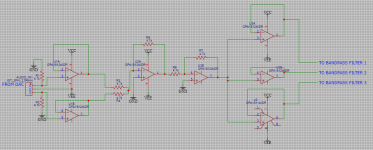
My schematic is the same, the only difference is that all resistors are 4.7Kohm and the output of the last OpAmp is connected directly to the inputs of three other OpAmps without resistor and capacitor.
There is another 4.7Kohm resistor from the output of the last OpAmp to ground as well.
And then, i will be able to use those three outputs for the bandpass filters + gain stages and that's it.
Thank you for all the info 😉
Post #2 and #3 actually have the answer with minimum parts count and complexity. The last circuit will certainly work...but...why? When two resistors will do it just fine? You don't have a PSU, you don't have capactitor type, polarity, polarizing voltage, and active parts to worry about. And the signal you get with two resistors will be identical in every way, except possibly better (if you want to obsess).
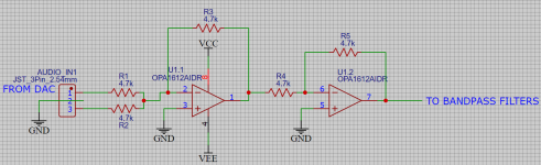
Anyway, this is my version of the schematic. I removed the capacitors because in the datasheet of the DAC i'm using, it says 'No DC blocking capacitors required'.
I used a voltage follower for both channels because my DAC can deliver very little current, and loading it will increase distortion.
I used a voltage follower for both channels because my DAC can deliver very little current, and loading it will increase distortion.
Attachments
Yep 🙂 and many variations are possible.
All I would add is that you could lose the two opamp buffers at the input. You have set the input impedance at 4k7 and the single opamp virtual earth mixer achieves that easily. One opamp should easily drive 3 bandpass filters and so you can get back from 7 opamps to 2.
All I would add is that you could lose the two opamp buffers at the input. You have set the input impedance at 4k7 and the single opamp virtual earth mixer achieves that easily. One opamp should easily drive 3 bandpass filters and so you can get back from 7 opamps to 2.
just add an buffer after the two resistors thenWhy does it say unbalanced mono? Does balanced mono exist and maybe its better?
Anyway, i wanted a solution with OpAmps because my load is pretty low impedance...
The OpAmps are powered with dual supply (±15V).
Alright, thank you.
I noticed i made a mistake in the schematic.
The ground of the audio source is connected to VEE because i mistaken it for GND. It should be connected to GND.
So, in the end... This new circuit should have the exact same audio performance and input impedance of the first one.
I noticed i made a mistake in the schematic.
The ground of the audio source is connected to VEE because i mistaken it for GND. It should be connected to GND.
So, in the end... This new circuit should have the exact same audio performance and input impedance of the first one.
Attachments
Yes just the same, but just be aware that a virtual ground will see all the opamp pins at 1/2 the rail supply voltage so you might need input and output coupling caps. It all depends how you couple it all together to other equipment. and whether the rail voltage comes from something floating (or not).
The dual supply of ±15V and GND is not floating, it's a proper dual supply, just like the one you can get from trasformers. To get it from a simple supply, i used two B2424S-3W voltage isolators, then added L7815 and L7915 to have a nice linear noise-free supply. It works and i have a ground, +15V and -15V that are completely isolated from the input supply.
I will add 1uF polypropilene capacitors on the left and right input.
I will add 1uF polypropilene capacitors on the left and right input.
Now everything should be alright.
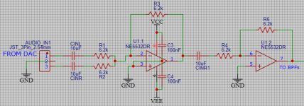
Capacitance increased to 10uF and resistors increased to 6.2K.
The problem is that it creates a high pass filter which would block 20 - 30Hz.
With theese values it passes from 30Hz and above with no amplitude drop.
Let me know if i solved all the problems.
Capacitance increased to 10uF and resistors increased to 6.2K.
The problem is that it creates a high pass filter which would block 20 - 30Hz.
With theese values it passes from 30Hz and above with no amplitude drop.
Let me know if i solved all the problems.
Attachments
- Home
- Source & Line
- Analog Line Level
- Best way to convert stereo signal to mono signal