I have simple horn loaded, rear vented cabinet model.
Why frequency reponse in Akabak and Hornresp differs?
I'm particularly interested in falling character of the Akabak response and in dB level offset.
I exported the akabak script from the Hornresp and manually rechecked all values in the LEM model.
The model parameters are identical in both softwares.
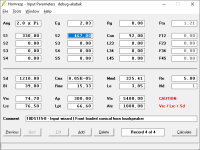
See models setup in screenshots.
For reference this is the hornresp generated Akabak script.
Why frequency reponse in Akabak and Hornresp differs?
I'm particularly interested in falling character of the Akabak response and in dB level offset.
I exported the akabak script from the Hornresp and manually rechecked all values in the LEM model.
The model parameters are identical in both softwares.
See models setup in screenshots.
For reference this is the hornresp generated Akabak script.
Code:
|DATA EXPORTED FROM HORNRESP - RESONANCES NOT MASKED
|COMMENT: 18DS115-8 - Input wizard | Front loaded conical horn loudspeaker
|~~~~~~~~~~~~~~~~~~~~~~~~~~~~~~~~~~~~~~~~~~~~~~~~~~~~~~~~~~~~~~~~~~~~~~~~~~~~~~~~~~~~~~~~~~~~~~~~~~~~~~~~
|REQUIRED AKABAK SETTINGS:
|File > Preferences > Physical system constants:
|Sound velocity c = 344m/s
|Medium density rho = 1.205kg/m3
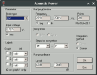
|Sum > Acoustic power:
|Frequency range = 10Hz to 20kHz
|Points = 533
|Input voltage = 2.83V rms
|Integration = 2Pi-sr
|Integration steps = 1 degree ... 1 degree
|Integration method = Cross
|~~~~~~~~~~~~~~~~~~~~~~~~~~~~~~~~~~~~~~~~~~~~~~~~~~~~~~~~~~~~~~~~~~~~~~~~~~~~~~~~~~~~~~~~~~~~~~~~~~~~~~~~
Def_Const |Hornresp Input Parameter Values
{
|Length, area and volume values converted to metres, square metres and cubic metres:
S1 = 330.00e-4; |Horn segment 1 throat area (sq m)
S2 = 467.00e-4; |Horn segment 1 mouth area (sq m)
L12 = 92.00e-2; |Horn segment 1 axial length (m)
Vrc = 74.70e-3; |Rear chamber volume (cubic m)
Lrc = 76.50e-2; |Rear chamber average length (m)
Ap = 300.00e-4; |Rear chamber port cross-sectional area (sq m)
Lpt = 66.60e-2; |Rear chamber port tube length (m)
Vtc = 5400.00e-6; |Throat chamber volume (cubic m)
Atc = 1000.00e-4; |Throat chamber cross-sectional area (sq m)
|Parameter Conversions:
Sd = 1210.00e-4; |Diaphragm area (sq m)
Rp = Sqrt(Ap / Pi); |Port tube radius (m)
Lpt1 = Lpt + 0.1952 * Pi * Rp; |Port tube length plus unflanged inlet end correction (m)
Arc = Vrc / Lrc;
Ltc = Vtc / Atc;
}
|~~~~~~~~~~~~~~~~~~~~~~~~~~~~~~~~~~~~~~~~~~~~~~~~~~~~~~~~~~~~~~~~~~~~~~~~~~~~~~~~~~~~~~~~~~~~~~~~~~~~~~~~
|Network node numbers for this horn-loaded vented-box system:
| 0-Voltage-1
| |
|Radiator(1)-3-Port-4-Chamber-5-Driver-6-Chamber-8-Segment-9-Radiator(2)
|~~~~~~~~~~~~~~~~~~~~~~~~~~~~~~~~~~~~~~~~~~~~~~~~~~~~~~~~~~~~~~~~~~~~~~~~~~~~~~~~~~~~~~~~~~~~~~~~~~~~~~~~
Def_Driver 'Driver'
Sd=1210.00cm2
Bl=39.00Tm
Cms=8.05E-05m/N
Rms=15.33Ns/m
fs=30.00Hz |Mmd = 325.41g not recognised by AkAbak, fs calculated and used instead
Le=3.85mH
Re=5.00ohm
ExpoLe=1
System 'System'
Driver Def='Driver''Driver'
Node=1=0=5=6
Radiator 'Port outlet'
Node=3
SD={Ap}
Label=1
Duct 'Rear chamber port'
Node=3=4
SD={Ap}
Len={Lpt1}
Visc=0
Duct 'Rear chamber'
Node=4=5
SD={Arc}
Len={Lrc}
Visc=0
Duct 'Throat chamber'
Node=6=8
SD={Atc}
Len={Ltc}
Visc=0
Waveguide 'Horn segment 1'
Node=8=9
STh={S1}
SMo={S2}
Len={L12}
Conical
Radiator 'Horn mouth'
Node=9
SD={S2}
Label=2Attachments

I am not familiar with running either code but a large difference at low frequencies which is relatively straightforward to simulate suggests a mistake in setting up one or both models. The 6 dBish size suggests it might be to do with the handling of rear and front radiation of the sources but this is a guess.
I'm particularly interested in falling character of the Akabak response and in dB level offset.
As indicated in the Help file Hornresp can export a script that can be used as input to 16-bit AkAbak Version 2.1. How the script is interpreted by later 32-bit versions of AKABAK is however problematic. For your example it seems that perhaps the AKABAK result is being calculated assuming quarter space rather than half space radiation conditions. If the input parameter values are the same then the Hornresp power response and AKABAK Lumped Element Method power response results should be identical.

I didn't import the akabak script - I used it only to recheck the parameters manually.
Parameters in Input Parameters window correspond with parameters in the exported Akabak script.
Akabak model parameters correspond with Input Parameters window and with the Akabak script parameters as well.
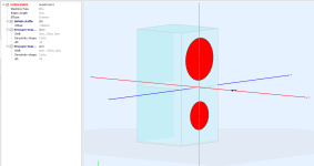
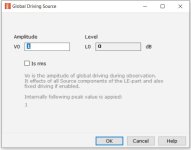
The radiation angle space should be defined in BEM as seen in screenshot. There are two radiators on infinite horizontal baffle, horn and port - that should simulate half-space radiation if I understand it correctly.
Will do further testing ...
Parameters in Input Parameters window correspond with parameters in the exported Akabak script.
Akabak model parameters correspond with Input Parameters window and with the Akabak script parameters as well.
The radiation angle space should be defined in BEM as seen in screenshot. There are two radiators on infinite horizontal baffle, horn and port - that should simulate half-space radiation if I understand it correctly.
Will do further testing ...
I was curious about those level differences. It's most likely your Akabak model.
I've attached both Akabak and Hornresp models (v2) that I used (roughly based on @Maple Mapleson pics. The levels and tuning look about the same. There will be differences in the "hash" because of differences in the front driver volume (cone vs flat) and port position relative to both driver and microphone. I did not put any effort in trying to match the interference hash from the models.
I've attached both Akabak and Hornresp models (v2) that I used (roughly based on @Maple Mapleson pics. The levels and tuning look about the same. There will be differences in the "hash" because of differences in the front driver volume (cone vs flat) and port position relative to both driver and microphone. I did not put any effort in trying to match the interference hash from the models.
Attachments
I did further testing with another simple front-loaded horn, rear vented enclosure.
@DonVK As you wrote there can be subtle FR differences when measuring FR in BEM model but when measuring in LEM model directly without the effects of mic distances the FR should be almost identical to the Hornresp model - see last VACS screenshot.
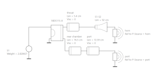
Hornresp schema

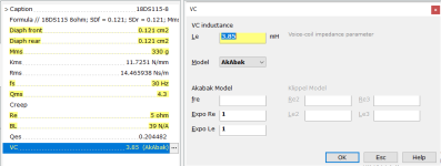
Hornresp parameters

Akabak LEM schema

Akabak BEM model with microphone position 30cm from the pressure sources

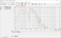
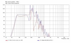
VACS FR for BEM microphone - Hornresp green, Akabak red

VACS FR for LEM, combined observation of an acoustic pressure in LEM radiator elements - Hornresp green, Akabak red

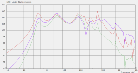
Comparison of BEM microphone, LEM microphone and Hornresp FR - all curves scaled to match levels in this graph.
LEM combined curve red, BEM microphone blue, Hornresp green

@DonVK As you wrote there can be subtle FR differences when measuring FR in BEM model but when measuring in LEM model directly without the effects of mic distances the FR should be almost identical to the Hornresp model - see last VACS screenshot.
Hornresp schema
Hornresp parameters
Akabak LEM schema
Akabak BEM model with microphone position 30cm from the pressure sources
VACS FR for BEM microphone - Hornresp green, Akabak red
VACS FR for LEM, combined observation of an acoustic pressure in LEM radiator elements - Hornresp green, Akabak red
Comparison of BEM microphone, LEM microphone and Hornresp FR - all curves scaled to match levels in this graph.
LEM combined curve red, BEM microphone blue, Hornresp green
Attachments
One more graph of the model from the previous post.
BEM ground measurement - mic 50cm horizontally from the pressure sources.

I would love to simulate LEM-only FR responses in various radiation angles but don't know if that's possible without using BEM.
BEM ground measurement - mic 50cm horizontally from the pressure sources.
I would love to simulate LEM-only FR responses in various radiation angles but don't know if that's possible without using BEM.
Last edited:
My sense is that you are comparing HR power response w/ BEM pressure (SPL)? A single pressure response for a double-output config isn't possible in HR (or is meaningless w/o distance between sources for combining, so David leaves it at each separate pressure response).
To do what you refer to (off-axis/polars), you will have to (externally) do curve arithmetic and export them one at a time from HR.
When you are in power response display, Tools->Output (choose Horn or Port)...this gets you Power for that but that's not what you want--it's step 1. Step 2 is Tools->Directivity->Response at which you may choose the angle for calculations. Export that and repeat.
Yes, this is laborious and dubious in value. It gets worse when you want to use walls and account for reflections differently for the lows and the highs and then merge those...but you get to find-out 🙂
I sligthly modified the BEM model. Now the pressure sources are in the same point.1. Set microphone distance to one metre.
2. Calculate power response.
Response shapes are identical but somehow there is 2 dB offset between them - Akabak response is 2dB down.
FR if mic distance set to 70cm
Last edited:
FR if mic distance set to 70cm
The AKABAK result is showing the pressure response, which takes directivity characteristics into account.
It should be possible to calculate the power response instead, which will then better match the Hornresp result at higher frequencies.
The results should be the same with a microphone distance of 100 cm, not 70 cm.
It would seem that there is still something wrong somewhere with the AKABAK input.
(For a perfect match it is necessary to use 533 data points and the Hornresp values for sound velocity and air density).
Last edited:
Matched sound velocity, matched air density, match 533 data points. The curve shape fits perfectly but there is still offset in the responses.
However I see that the reference value for sound pressure in Hornresp is 20 micropascals meanwhile in Akabak it's p0 = √2·20µPa and this is what probably makes an dB offset.
If I take sample pressures at a single frequency and convert them to same reference pressure scale they match.


However I see that the reference value for sound pressure in Hornresp is 20 micropascals meanwhile in Akabak it's p0 = √2·20µPa and this is what probably makes an dB offset.
If I take sample pressures at a single frequency and convert them to same reference pressure scale they match.
I see that the reference value for sound pressure in Hornresp is 20 micropascals meanwhile in Akabak it's p0 = √2·20µPa
The generally-accepted standard reference pressure is 20 micropascals rms, with the SPL being calculated at a distance of 1 metre from the source. I have no idea why AKABAK should choose to use the equivalent peak value instead as the reference.
AKABAK is calculating the SPL in decibels as:
SPL = 20 * Log10(p / ((2 ^ 0.5) * pref))
SPL = 20 * Log10(1 / (2 ^ 0.5)) + 20 * Log10(p / pref)
SPL = -3.0103 + 20 * Log10(p / pref)
Which is why the AKABAK result is offset from the Hornresp result by -3dB.
- Home
- Design & Build
- Software Tools
- Akabak LEM vs. Hornresp model different FR