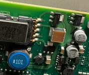
This is from the car radio / sat nav unit of a 2014 Ford Galaxy / S-Max. Those units were introduced after the 2010 face lift and were made by Blaupunkt (Bosch). The units emit a high pitched noise from the screen and through the CD slot (7.9, 9.9 and 15.8 kHz). Apparently, the power supply for the CCLD does this. There is no good way to power the PCB when it is disassembled, so I am not sure how the guy who posted the picture below identified the components. His guess was it came from the electrolytics or the large MLCC cap that he misidentified as a coil.
My guess it is the MLCC or the transformer (the windings are not secured by tape or lacquer.
Anyway, I desoldered the large cap without doing a prior in circuit measurement. The contact plates started gliding on the cap when I did this. Afterwards I measured 8.5 nF which seems way to small. I tried floating the plates back i place but that resulted in even lower readings.
So what could the case size be? It is about 7 mm long, 6.4 mm wide and 4.8 mm high. This is a little off from the 2924 case often used for solid tantalum caps (7 .3 mm x 6 mm).
Once I know what the size is, I will have to find out what capacitances were available in that case back in or before 2010. I am guessing the operating voltage will be 12 or 5 V.
Mouser's selection guide tells me there are Kyocera 10 µF 25 and 50 V X7R caps in a metric 7361 case, but my case is a little too short and too wide for that (just confirmed with digital calipers)
(edit: that case also looks quite different https://www.mouser.de/datasheet/2/40/MH_CeramicCapacitor-3165541.pdf)
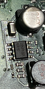
The large cap connects the large contacts of the two transistors (?) sitting right next to the transformer. They are marked 435ZDG. The other transistor like thing seems to be a voltage regulator and is marked RAV117AV.
https://www.motor-talk.de/forum/navi-nerviges-fiepen-t4268623.html
https://www.motor-talk.de/bilder/navi-nerviges-fiepen-g77078414/004-i208918361.html
My guess it is the MLCC or the transformer (the windings are not secured by tape or lacquer.
Anyway, I desoldered the large cap without doing a prior in circuit measurement. The contact plates started gliding on the cap when I did this. Afterwards I measured 8.5 nF which seems way to small. I tried floating the plates back i place but that resulted in even lower readings.
So what could the case size be? It is about 7 mm long, 6.4 mm wide and 4.8 mm high. This is a little off from the 2924 case often used for solid tantalum caps (7 .3 mm x 6 mm).
Once I know what the size is, I will have to find out what capacitances were available in that case back in or before 2010. I am guessing the operating voltage will be 12 or 5 V.
Mouser's selection guide tells me there are Kyocera 10 µF 25 and 50 V X7R caps in a metric 7361 case, but my case is a little too short and too wide for that (just confirmed with digital calipers)
(edit: that case also looks quite different https://www.mouser.de/datasheet/2/40/MH_CeramicCapacitor-3165541.pdf)
The large cap connects the large contacts of the two transistors (?) sitting right next to the transformer. They are marked 435ZDG. The other transistor like thing seems to be a voltage regulator and is marked RAV117AV.
https://www.motor-talk.de/forum/navi-nerviges-fiepen-t4268623.html
https://www.motor-talk.de/bilder/navi-nerviges-fiepen-g77078414/004-i208918361.html
Last edited:
Hi, you could try a few drops of slow curing epoxy on the transformer. Point being that first a root cause analysis is necessary otherwise it is trial & error. Also OK but costs more time.
The cap could have been defective before you soldered it. This can be seen more often when mechanical tension is on PCBs or SMD ceramic caps. Then at one side the complete metal contact comes loose (which can not be seen unless the cap is desoldered). You probably need to ask Bosch what cap was used. Maybe replacing it solves the issue.
It can very well be a combination of issues. Nice challenge!
Last edited:
Well, I was hoping the cap could be identified by its unusally sized case.
The high pitched noise seems to be present in all those units. In the thread I linked, there were folks who had gone through several replacements, and had also listened to all cars in the showroom with that model of radio installed.
The high pitched noise seems to be present in all those units. In the thread I linked, there were folks who had gone through several replacements, and had also listened to all cars in the showroom with that model of radio installed.
Yeah things go like that. I like to solve such issues as it is swimming against the stream. That is refreshing and solution seeking orientated. What laymen all may say rarely leads to a solution.
Best is to take it apart, make a test situation and send an email to Bosch for the brand and type of cap. Maybe they support you with a schematic too. They surely know what the cause is but probably did not like to fix/replace all the affected devices 😉
A telephone call might be more effective than an email. The cap seems a special one, maybe an ultra low ESL film cap even (looks like ceramic, I know).
Last edited:
Well, I am sure it is a ceramic multilayer cap. The contact plates look a bit like the old Siemens MKT, but are thinner. The cap body is a lot harder and does not melt when poked with a soldering iron.
Then it is ceramic. Still an unusual one. Maybe extra high voltage or the like as it is in the oscillator circuit to create the voltage for the backlight (it seems). Also a chance of it being piezoelectric so highly suspect. Gambling which one it may be is not the right way. Spend a few minutes contacting Bosch/Blaupunkt.
Last edited:
Seems to be pretty much this circuit. The cap connecting the collectors was a giveaway.
https://danyk.cz/ccfl_en.html
So I am really looking for medium sized capacitance and largish voltage rating.
https://danyk.cz/ccfl_en.html
So I am really looking for medium sized capacitance and largish voltage rating.
Yes except that you are not really looking for a medium sized capacitor with largish voltage rating as that are 2 variables 🙂 For that particular/specific circuit.
IMHO it really would help to know the original value and working voltage for a good starting point for both repair and a fix for the noise.
IMHO it really would help to know the original value and working voltage for a good starting point for both repair and a fix for the noise.
Last edited:
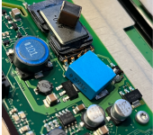
I replaced it with a 200 nF / 350 V Siemens molded film cap and dripped some isolating lacquer into the windings of the transformer. It seems much quieter now, I can only hear it when I almost place my ear on the display or the CD slot. But then, it is raining all day, so hard to tell.
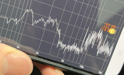
Measuring with a smartphone app, I need to hold it right onto the unit but then, the main components of 7.9 and 15.8 kHz are still there (about 40 and 30 dB above noise background). The sporadic 9.9 kHz peak is gone or replaced by a carpet of needles.
Unless I accidentally chose exactly the right capacitance, the frequency should have changed, but it didn't. Can't see an IC that injects a frequency either.
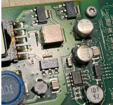
@bikeron, the large brown thing next to the transformer and between the two transistors is the culprit. The unidentified ST IC does not seem to be the controller for the inverter circuit. It's probably a voltage regulator for the FPGA that lives to its right.
Measuring with a smartphone app, I need to hold it right onto the unit but then, the main components of 7.9 and 15.8 kHz are still there (about 40 and 30 dB above noise background). The sporadic 9.9 kHz peak is gone or replaced by a carpet of needles.
Unless I accidentally chose exactly the right capacitance, the frequency should have changed, but it didn't. Can't see an IC that injects a frequency either.
@bikeron, the large brown thing next to the transformer and between the two transistors is the culprit. The unidentified ST IC does not seem to be the controller for the inverter circuit. It's probably a voltage regulator for the FPGA that lives to its right.
Attachments
No, that's not how SMPS's generally work, the control IC does the timing, L and C provide energy storage. The SMPS is likely high up in the ultrasonic range, your spikes could be sub-harmonics. And yes a ceramic type II caps can sing like this (although the transformer might be the cause). You changed both at the same time so don't know which was the culprit! Mind you looking at the PCB it looks fairly complex, might be SMPS (several topologies possible), class D output stage...Unless I accidentally chose exactly the right capacitance, the frequency should have changed,
But given the description my best guess is a resonant converter SMPS, so you might have taken the thing out of resonance even?
I have not fully analyzed the circuit but I think I have seen all the elements of the circuit linked in post #7 (which I believe is also known as Royer's oscillator. In particular, the mystery cap connects the collectors of the transistors.
The funny thing is that I did not change the resonant frequency of 7.9 kHz and its 2nd harmonic. I may have introduced some spuriae between these frequencies but it is years that I had measured the spectrum of the noise.
The funny thing is that I did not change the resonant frequency of 7.9 kHz and its 2nd harmonic. I may have introduced some spuriae between these frequencies but it is years that I had measured the spectrum of the noise.
Almost need to find one that hasn’t failed yet and try and measure the capacitor.
Hats off for being one of the brave souls who dare to meddle with an oem head unit.
I do wish more information was available for those, would definitely make it easier to repair them. The fact that it is less noisy now makes me also wonder if it’s still working as intended or if the new part is damping it.
- Home
- Design & Build
- Parts
- very large MLCC cap from CCLD supply, what value could it be?