Hi everyone,
I’m working on restoring my father in law’s TL12s and would love some input and advice. I have two amps and a spare third chassis with missing ironware and a mix of new and old components. There is also a Point One preamp and Troughline tuner but I am not looking at those.
The amps were last tested 20 years ago but were almost certainly in storage before that.
I have a multimeter and new digital LCR meter, and old (untested) CRT oscilloscope but no other proper test equipment.
What I’ve done so far:
Questions and next steps:
1. The 4uF+8uF+4uF capacitors in the can show no signs of leakage. The LCR meter shows nominal values (3600nF-4100nF, 7800-7820nF and Vloss 0.1% ESR 0.5 Ohms for each). What else do I need to do to test if these are ok to use? Or should I just bypass them with modern caps?
2. I am planning to replace the 5 coupling capacitors in each amp with 0.27uF 630V polypropylene from Cornell Dubelier. I can’t find a reliable source of high voltage 0.25uF capacitors anywhere. Is this a sensible choice?
3. I will replace all the electrolytics with identical values, and any resistors that are out of tolerance according to the list on 44bx.com
4. How can I further test the ironware? I am getting very low resistances (MM shows about 0.5 Ohm) on the mains transformer low voltage secondaries which makes sense to me. I am also getting very low resistances on the outputs secondaries (about 0.5 Ohm).
5. The output transformers are wired for 8 Ohms impedance, but the associated resistor/capacitors are the 32 Ohms options. Maybe the transformers were rewired at some point? Is this a problem?
6. One amp has no R23 in the circuit going to the cap of the preamp valve. It just has a wire going direct to the valve cap. Should I change that? The other amp has a potentiometer in the input circuit and I haven’t worked out what is going on there yet.
5. What advice is there on powering up safely once the steps above (and any others) have been addressed?
6. What else have I missed

I’m working on restoring my father in law’s TL12s and would love some input and advice. I have two amps and a spare third chassis with missing ironware and a mix of new and old components. There is also a Point One preamp and Troughline tuner but I am not looking at those.
The amps were last tested 20 years ago but were almost certainly in storage before that.
I have a multimeter and new digital LCR meter, and old (untested) CRT oscilloscope but no other proper test equipment.
What I’ve done so far:
- read the very helpful advice at 44bx.com
- remove the ironware and test for DC continuity with multimeter. One of the chokes has gone open circuit but luckily there is a spare in the box of stuff I was given.
- clean up the amp chassis
- test the capacitors and resistors in circuit using an LCR meter.
Questions and next steps:
1. The 4uF+8uF+4uF capacitors in the can show no signs of leakage. The LCR meter shows nominal values (3600nF-4100nF, 7800-7820nF and Vloss 0.1% ESR 0.5 Ohms for each). What else do I need to do to test if these are ok to use? Or should I just bypass them with modern caps?
2. I am planning to replace the 5 coupling capacitors in each amp with 0.27uF 630V polypropylene from Cornell Dubelier. I can’t find a reliable source of high voltage 0.25uF capacitors anywhere. Is this a sensible choice?
3. I will replace all the electrolytics with identical values, and any resistors that are out of tolerance according to the list on 44bx.com
4. How can I further test the ironware? I am getting very low resistances (MM shows about 0.5 Ohm) on the mains transformer low voltage secondaries which makes sense to me. I am also getting very low resistances on the outputs secondaries (about 0.5 Ohm).
5. The output transformers are wired for 8 Ohms impedance, but the associated resistor/capacitors are the 32 Ohms options. Maybe the transformers were rewired at some point? Is this a problem?
6. One amp has no R23 in the circuit going to the cap of the preamp valve. It just has a wire going direct to the valve cap. Should I change that? The other amp has a potentiometer in the input circuit and I haven’t worked out what is going on there yet.
5. What advice is there on powering up safely once the steps above (and any others) have been addressed?
6. What else have I missed
Attachments


You've probably discovered that TL12 go for big money. Almost any work you do on them will dramatically reduce their value. It all depends on whether you want to sell them or use them. A low voltage test won't show if the smoothing capacitors are about to fail. Nevertheless, paper coupling capacitors are almost certain to be leaky and need to be replaced. 220nF 1kV polypropylene will do fine. Most people would bring each amplifier up gently on a Variac while watching the voltage at the centre tap of the output transformer and sniffing for nasty smells. Bear in mind the amplifiers are probably 60 years old and are bound to have a fault or two. Probably the most important thing is to ensure that they are properly earthed. If I remember correctly, the TL12 have a large three-pin mains socket with solder tags screwed to the pins. There's often high resistance between the pin and the tag and the same will be true on the tag down to the chassis. Valves operate at dangerous voltages and you need to know what you are doing when poking inside or they can kill you.
Safety first around regarding working with lethal High Voltages AC and DC.
If you are an old hand, who inspects the DVM leads for cracks or nicks to the insulation, sensibly keeps their left hand in his pocket whilst taking measurements on live equipment. Consider the use of bleed resistors across the PSU caps etc, please accept my apologies for mentioning this point.
The chassis looks fairly rusty, it might be useful to go over earthing and grounding to verify low impedance paths, maybe some dismantling of assembly screws and cleaning up metalwork where connections to chassis or earth is needed.
Only one fuse?
Maybe others will suggest fusing the HT, not sure on that one personally as it will no longer be original. However, if you are going to change R, and C's where they are out of spec that would invalidate originality to some.
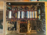
I can see EL37 in one image.
I cannot remember if its a known good replacement for KT66's Check resistor's to see if any have been changed to accommodate or allow fitting of them.
Variac and light bulb approach, to give the PSU Caps and other a gentle re awakening. I am sure other more valve aware people will detail their proven power up cycle.
You will need to figure out input resistance and gain pot on the input and decide on a sensible choice on how to replace the resistor capacitor input combination. I don't know if you might consider intentionally having a LF roll off to help not saturate the output transformers?
I haven't a clue about the transformer aspect you mention. It maybe that they were simply used for two different applications one more modern 8 ohms and the other Higher impedance?
If you are an old hand, who inspects the DVM leads for cracks or nicks to the insulation, sensibly keeps their left hand in his pocket whilst taking measurements on live equipment. Consider the use of bleed resistors across the PSU caps etc, please accept my apologies for mentioning this point.
The chassis looks fairly rusty, it might be useful to go over earthing and grounding to verify low impedance paths, maybe some dismantling of assembly screws and cleaning up metalwork where connections to chassis or earth is needed.
Only one fuse?
Maybe others will suggest fusing the HT, not sure on that one personally as it will no longer be original. However, if you are going to change R, and C's where they are out of spec that would invalidate originality to some.
I can see EL37 in one image.
I cannot remember if its a known good replacement for KT66's Check resistor's to see if any have been changed to accommodate or allow fitting of them.
Variac and light bulb approach, to give the PSU Caps and other a gentle re awakening. I am sure other more valve aware people will detail their proven power up cycle.
You will need to figure out input resistance and gain pot on the input and decide on a sensible choice on how to replace the resistor capacitor input combination. I don't know if you might consider intentionally having a LF roll off to help not saturate the output transformers?
I haven't a clue about the transformer aspect you mention. It maybe that they were simply used for two different applications one more modern 8 ohms and the other Higher impedance?
If 'm reading the schematic and strapping table correctly, the feedback resistor and cap values should conform to the appropriate output impedance wiring. It's possible that at some point someone change the output to 8 ohms but failed to change the feedback network. In that case the feedback would be dramatically reduced and the amp would sound the worse for it.
Amazing amps, BTW, never seen them before. I would probably bypass the capacitor module with modern film caps, mounting them on tag strips and leaving the original case in place, obviously.
Yes, I would replace all the coupling caps. C-D 942C series are very good caps and come in 1000VDC versions, but 630VDC is fine, I think. .22uF would suffice and would be easier to find.
As for restoring/modifying them, IMO there's little point in an amp that is likely to fail at some point in the very near future, destroying ANY value it might have. If I were buying them I would want them operating safely and up to spec. But that's your call. ;-)
I have done lot of repair-refurb on these old stuff.I’m working on restoring my father in law’s TL12s
To back them at the best you can replace all caps and resistor; they are a low quality components and vary the value with time killing the sound.
You can bring the old parts in a bag if someone want to buy the amp.
Then you can check the tensions on each part of circuit.
In this way the amp has a new beautiful life.
Walter
I agree. Replace all the resistors. The originals have no special value. Buyers want something that works and will stay working, but without circuit modifications.
R23 is a grid stopper and should be present. It’s an anti-oscillation measure.
R23 is a grid stopper and should be present. It’s an anti-oscillation measure.
What is your reason for asserting that? They’ve already lasted at least 67 years so far.there's little point in an amp that is likely to fail at some point in the very near future
Old capacitors are a ticking time bomb. Old carbon comp resistors drift and become noisy. I was restoring an old Sansui solid state amplifier and one channel was reading high distortion relative to the other. Tracked it down to one resistor on the input stage that was just slightly out of tolerance. Replaced it and the THD dropped from over 1% down to 0.05.
Of course they are, and ditto carbon composition resistors, but that's not an argument against restoration. What you actually wrote was:Old capacitors are a ticking time bomb ...
You are arguing in circles.As for restoring/modifying them, IMO there's little point in an amp that is likely to fail at some point in the very near future
I think you've confused me another commenter. And perhaps my own comment wasn't clear. I was trying to say that a restoration would, IMO, be preferable to trying to operate the amps in their present condition. They haven't, in fact, been working for 67 years. The OP says they were last tested 20 years ago, and were in storage before that. Why risk trying to run valuable amps with aged components that might fail at any time, especially if they've been sitting unused for a long period of time?
Last edited:
... plus the valuable time that is wasted fixing things twice.Why risk trying to run valuable amps with aged components that might fail at any time, especially if they've been sitting unused for a long period of time?
Some people would even painstakingly replace the insides of the old components with new ('stuffing' to retain the original appearance), but I think anything that improves reliability and performance is acceptable under the chassis, as long as it can be reversed if needs be.

Langford-Smith did the test of these highly rated amps in Radiotronics magazine, can be found on the net in :
1955_09_AWV_Radiotronics_20_09
1956_06_AWV_Radiotronics_21_06
P.S. Too big to upload but interesting reading, these were not "tests" of todays reviewers.
1955_09_AWV_Radiotronics_20_09
1956_06_AWV_Radiotronics_21_06
P.S. Too big to upload but interesting reading, these were not "tests" of todays reviewers.
They are fantastic with old Tannoys ( red and silver series.) They will never be a modern amp pleasing " resolution " type folks. I would sell them as is to collector after lengthy variac cycle of warming them up . Unless you can afford to loose quite a bit of money to keep family heirloom you may not really enjoy. I've been down the road upgrading vintage " ticking bombs" only to get less money than original rusted out junk to advocate any surgery to collectible memorabilia. That stuff is only original once .
Imho, it's worth taking your time to clearly list out your issues and how you would approach them and why, before starting on any power up activity. It's good to see you are posting on vintage-radio.net, as that is also a wealth of experience for this type of amp. I'd also suggest using google to chase down as many insights etc as you can - such as Patrick Turner's restoration, and how to make your amps more 'bullet proof'.
I don't think you have clarified your position on restoration, and why. It seems like you appreciate you need to replace some parts and make the units safe, and so trying to make the amps 'as close to original condition as possible for resale' is not your motivation. I'd support that outlook, and go further and suggest you also look at ways to subtly make the amp less likely to fail and damage parts in the future - that is a path not often taken as some are concerned the amp is then not original. As valves and parts do fail over time, avoiding collateral damage to power and output transformers and chokes is imho well worth the effort, and may take some time to appreciate what can be done and how.
I don't think you have clarified your position on restoration, and why. It seems like you appreciate you need to replace some parts and make the units safe, and so trying to make the amps 'as close to original condition as possible for resale' is not your motivation. I'd support that outlook, and go further and suggest you also look at ways to subtly make the amp less likely to fail and damage parts in the future - that is a path not often taken as some are concerned the amp is then not original. As valves and parts do fail over time, avoiding collateral damage to power and output transformers and chokes is imho well worth the effort, and may take some time to appreciate what can be done and how.
I doubt you have tested these to rated dc voltage levels and confirmed negligible leakage through each cap ? It would also be wise to test them for leakage to case at rated voltage levels. Without a megger, you could attempt to do that during initial power up, but that would require a carefully prepared set of conditions to allow measurement of the likely leakage paths, and would I suggest need to use a variac and a dummy ss rectifier and current limit and sense resistors - but well worth it to confirm the health (or not) of that combo cap assembly. Even if one cap was identified as being leaky, the leaky part can be bypassed and the good caps still used - I have done that for a similar B.I.Callenders combo in a Goodsell GW18 Williamson of similar vintage.1. The 4uF+8uF+4uF capacitors in the can show no signs of leakage.
I'd also suggest using google to chase down as many insights etc as you can - such as Patrick Turner's restoration, and how to make your amps more 'bullet proof'.
I’m interested in views on the Patrick Turner changes https://www.turneraudio.com.au/leakampmods.html
- Increased cathode resistances I can make a decision once things are up and running and measured
- Increased filter capacitance…is there a risk of overloading the rectifier tube?
- Lots of changes to feedback networks that I didn’t understand
- The OPT protection circuit looks interesting but I’ve not seen anything like this elsewhere
Lot's of 'learning curve' required for this type of restoration imho. You'll google a lot of posts relating to how much capacitance can be used, and simulators like PSUD2 that can help. Another reference that may identify some more issues to be aware of before and whilst powering up with your Ravistat : https://www.dalmura.com.au/static/Renovating PA amps.pdf.
- Home
- Amplifiers
- Tubes / Valves
- Leak TL12 Restoration