Hi, everyone! Hope you're all doing fine.
I'm implementing a motional feedback system for a subwoofer which is based on recovering the driver's Back-EMF and feeding it back to the amplifier, so the driver's Qts can be effectively lowered. That would, theoretically, alllow me to obtain a flatter response, extending further towards the infrasonics, with a smaller enclosure.
The problem is: to stiffen up the suspension through electrical means, whilst maintaining peak SPL, I'll need to supply more power to the driver. That wouldn't be a problem per se, if I weren't already planning to run the driver at its average (or "RMS") power limits.
The question is: from your personal experience, how far can we push the peak power delivered to a subwoofer (given that we respect both its excursion as well as its average power limits) before it suffers mechanical damage from excessive motor force?
About the Driver
The driver is an 18WP600 from JBL. Its specs are as follows:
About the Power Amplifier
The amplifier will be a custom Class-D power amplifier. Its relevant features are:
About the Motional Feedback
The new desired speaker parameters are:
The feedback will consist of (see picture attached):
I'm implementing a motional feedback system for a subwoofer which is based on recovering the driver's Back-EMF and feeding it back to the amplifier, so the driver's Qts can be effectively lowered. That would, theoretically, alllow me to obtain a flatter response, extending further towards the infrasonics, with a smaller enclosure.
The problem is: to stiffen up the suspension through electrical means, whilst maintaining peak SPL, I'll need to supply more power to the driver. That wouldn't be a problem per se, if I weren't already planning to run the driver at its average (or "RMS") power limits.
The question is: from your personal experience, how far can we push the peak power delivered to a subwoofer (given that we respect both its excursion as well as its average power limits) before it suffers mechanical damage from excessive motor force?
About the Driver
The driver is an 18WP600 from JBL. Its specs are as follows:
- Fs: 35Hz;
- Vas: 294L;
- Qts: 0.46;
- Qes: 0.48;
- Qms: 20,4;
- AES Power: 1200W [300W average (or "RMS")].
About the Power Amplifier
The amplifier will be a custom Class-D power amplifier. Its relevant features are:
- 8-Ohms output impedance;
- PSRR-enhanced, fully feedforward architecture;
- Average power capped by the PSU at 300W, peak power supplied by the bulk capacitors;
- Peak power still to be determined. Crest factor is expected to be anything between 6dB and 10dB.
About the Motional Feedback
The new desired speaker parameters are:
- 0.25 <= Qts <= 0.3.
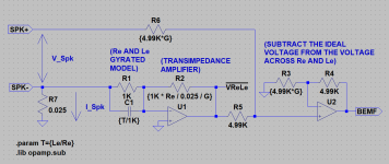
The feedback will consist of (see picture attached):
- Sensing the voltage across the driver, VSpk, as well as the current through it, ISpk;
- Feeding a voltage representation of ISpk through a gyrated model of the RL network represented by the speaker's Re and Le to a transimpedance amplifier, obtaining a representation of the voltage across it, VReLe;
- Subtracting VReLe from the scaled-down version of VSpk, obtaining a representation of the back-emf, VBEMF;
- VBEMF is amplified and summed/subtracted to/from the signal fed to the power amplifier, according to increase/reduction in Q required.
Attachments

Depends on various aspects. Great druvers normally handle 4x AES/RMS power value.
You cannot change specs inherent to the driver, you can only emulate.
Though you are doing awesome stuff. Best of luck.
You cannot change specs inherent to the driver, you can only emulate.
Though you are doing awesome stuff. Best of luck.
Class D and Motional Feedback are difficult bedfellows, I had to go back to Class AB for ease of stabilising the loop.
I found that a Hypex UCD is not a drop-in replacement for the previous AB amplifier, although the voltage gain was the same, and didn't want to spend the time trying to stabilise the loop.
I am currently building a motional feedback subwoofer using an ACH-01 accelerometer and a Honey Badger amplifier, because Class AB is easier.
With grit and determination you might find a way to solve the issues - report back if you do.
Thank you for your input, @Crashpc. The driver seems to be of reasonable quality. What concerns me the most is the cone, which is pressed.Depends on various aspects. Great druvers normally handle 4x AES/RMS power value.
Yeah! That's pretty much what I'm hoping to achieve: emulate a driver with a lower Qts. Gotta work with what I have, right? 😉You cannot change specs inherent to the driver, you can only emulate.
@johnnyx, indeed. Phase shift can be a real issue. My class-d amplifier is inspired on the BCA topology by Crown (figure 1), and I've measured the delay to be in the order of a few microseconds (unlikely to significantly affect loop stability). The amplifier also operates in an open-loop, with the rail voltage directly modulating the amplifier's gain in a feed-forward manner (figure 2), so loop interaction can be safely ruled out, too.Class D and Motional Feedback are difficult bedfellows, I had to go back to Class AB for ease of stabilising the loop.

Figure 1 - the output stage arrangement: two buck converters, operating in a push-pull configuration

Figure 2 - the input stage: a voltage-controlled attenuator directly modulated by the rail voltage
I've also modeled and simulated the whole loop (figure 3) and here are a few of the graphs from the simulation:

Figure 3 - The whole loop modeled

Figure 4 - The audio input and the recovered back-EMF for different feedback gains (0 to 1 in 0.2 increments)

Figure 5 - The power consumed by the driver for different feedback gains (0 to 1 in 0.2 increments)

Figure 6 - The curve for the back-EMF's amplitude for different feedback gains (0 to 1 in 0.2 increments)

Figure 7 - The recovered back-EMF laid on top of the "real" back-EMF
Edit: for completeness, here go two more images:

Figure 8 - the driver model subcircuit

Figure 9 - the back-EMF recovery subcircuit
Last edited:
Yamaha used positive current feedback to cancel the voice-coil resistance, by giving the amplifier a negative output resistance, I forget what it was called.
They had a temperature-compensating resistance to sense the current, because voice-coil resistance increases with temperature.
I accidentally had this arrangement when I used remote-sensing, the wiring to the speaker became the current-sensing resistance.
The amplifier's control over the speaker was improved, but it would have varied with power.
Might work with Class D. There are many threads on Motional Feedback - did you search?
Last edited:
Oh, snap! There's that, too. I wonder how accurately the VC temp can be estimated from the power delivered by the amplifier alone, given that the majority of the power seems to be wasted into the series resistance.They had a temperature-compensating resistance to sense the current, because voice-coil resistance increases with temperature.
The temperature of a heating element for sealing plastic bags can be estimated through measurements of voltage and current, giving its resistance at a specific temperature, and there are temperature controllers designed to do exactly that, but in the case of a loudspeaker, the emfs get in the way.
- Home
- Loudspeakers
- Subwoofers
- Back-EMF Motional Feedback / Amplifier Maximum Power Rating