After much trial and error, wasting materials, making mistakes, refinements, buying multiple versions of connectors, and many stupid mistakes... I've become somewhat of an expert at making high voltage umbilical connectors for separating a tube power supply from the amplifier. I wanted 10 conductors to cover many designs in the future. I also wanted to be able to send AC filament voltage across without inducting hum, so each cable has a twisted pair of 16 AWG that is shielded in a Belden-foil cable, this shield also has a 16 AWG drain wire which doubles to carry the safety ground from the PSU to the device, safety first. This leaves 7 more conductors. For the shorter cables (16 and 24 inch versions) I ran 20 AWG mil-spec silver teflon wires for these 7. For the longer cables (36 and 48 inches) these 7 conductors are 18 AWG silver teflon mil-spec wires. The designer can use these pins however they want. The designer can use a 36 or 48 inch cable to keep the "power brick" on the floor hidden. The shorter cable (16 inch) can be used when you want the PSU right next to or under the amp. The shield for the heater conductors (16 AWG) is dedicated as the safety ground transfer, and doubles to shield the AC heater from the other wires in the harness. Or you can run high-current DC filaments on these 16 AWG wires. The outer jacket of it all is made of 17mm OD 12mm ID latex laboratory tubing, very flexible, with high dielectric strength. The aircraft connectors themselves are rated to 500VAC / 700VDC but I would keep it under 500 because any wire also has to have a good rating. The connectors are 30mm diameter with 10 gold pins. I used a lot of high heat to solder the wire cups to make sure there were no cold joints, and heat-shrunk each solder cup inside the shell. Pulling the wire through the latex jackets, involves spraying some dry lube silicone on the wires, then using a fiberglass fish tape to pull the whole thing into the outer jacket. For the chassis connectors, you'd use the female connector on the PSU and the male on the amp, these attach with 4 screws in a 30mm hole, similar to how XLR connectors attach. I have some plastic hang-tags coming where I'll label the pins as to their wire gauge and if they are the shielded pair. I had to but a bunch of aircraft connectors to get the price break, so I'm on a roll making more of these than I'm likely to ever use. 10 conductors, but depending on the design an extra conductor can be had by finding the opportunity to share a ground, etc.
16 and 24 inch long cables pin configuration:
Pins 1 through 7 - 20 AWG silver/teflon mil spec (purpose as needed)
Pins 8 and 9 - 16 AWG Belfoil shielded twisted pair (typically for heater circuit) (high quality Belden cable used here)
Pin 10 - Shield drain wire (you must use this pin to carry the safety ground across so that both your chassis have a safety ground)
36 and 48 inch long cables pin configuration (thicker gauge is used here):
Pins 1 through 7 - 18 AWG silver/teflon mil spec (purpose as needed)
Pins 8 and 9 - 16 AWG Belfoil shielded twisted pair (typically for heater circuit) (high quality Belden cable used here)
Pin 10 - Shield drain wire (you must use this pin to carry the safety ground across so that both your chassis have a safety ground)
Voltage rating (using PTFE insulated wire)
Pins 1 through 7 - PTFE wire is rated 600VAC 840VDC, the connector itself is rated 500VAC 700VDC, therefore the whole cable is rated 700VDC if built as shown.
Pins 8 and 9 - The Belden cable used here is rated 300VAC 420VDC but is meant to be used for the low voltage heater.
Pin 10 - This is the safety ground, it should not be carrying any load
Last edited:

Impressive.
This kind of connectors must be expensive. A cheaper alternative of the same quality would be Russian military connectors. Screw-on connectors are also very reliable.
I use one connector per cable - at the power supply. The other end permanently soldered to amplifier.
I use permalloy tape to shield wires carrying AC.
Chinese made connectors are decent enough anymore. We use different types of mil spec connectors at my job and the prices have varied widely since the pandemic. One of our good manufacturers (RMS) was bought by a big company and the quality dropped so badly that the government ordered them to shutdown and fix their problems. Now we have to buy them surplus when they show up to support existing customer equipment. I had a chuckle because we bought some connectors recently with an 02/1980 manufacturing date!
I also use Russian military connectors (leftovers from the Cold War), but Amphenol military series (like 62LC) also good.
Not expensive connectors at all considering they sell you the chassis and cable sides as a pair for under 8 bucks.
Here is the male (cable) to female (chassis) connector (this pair on the PSU side)
https://www.aliexpress.us/item/3256...t_main.18.2b4d1802Cam9Dr&gatewayAdapt=glo2usa
Here is the female (cable) to male (chassis) connector (this pair on the amplifier side)
https://www.aliexpress.us/item/3256...t_main.19.2b4d1802Cam9Dr&gatewayAdapt=glo2usa
I tried many versions of connectors, this series goes up to even larger diameters. But I found that this 30 mm size in the 10 pin count has nice thick pins and a good amount of separation between them. With the next diameter up you'd be having to manage a long wide connector behind your amp. up against the wall. They do have the needed voltage rating for anything I'm going to do. When I apply the plastic hang tags with the wiring explanation I'll derate the voltage in case anyone inherits these after I'm dead.
Some tips, for anyone making these. Building the first side is very easy because there is no "other side" yet to block work or get you painted into a corner. To do the "other side" follow these steps:
1) Make sure the shell and locking ring are squeezed onto the jacket and positioned thread side out. A stupid common mistake is to solder then realize you didn't put the shell on the damn cable first.
2) Trim the wires so they are all even and extend about 1 inch past the outer latex end. Strip them to the depth of the solder cups, tin if needed.
3) Now make a 1.5 inch longitudinal cut in the latex tubing so that you can fold it backwards to expose more wire, temporarily put a hose clamp or zip tie or something to keep it folded back. You do this because you need the outer jacket to wind up "in the shell" but you also need more than the measly one inch of the wires showing to solder and get the heat shrink on.
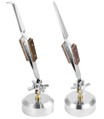
4) I used tweezers mounted on an iron stand to hold each wire in its solder cup (see below). The connector end mounted in my bench vise in rubber jaw protectors.
5) Push some heat shrink on each wire before soldering, push it back good and far so that soldering doesn't shrink it. Push the flux pen on each pin before soldering (see below).
6) After everything is soldered push all your heat shrinks over the solder cups. Shrink them so that they shrink over the wire prior to shrinking over the solder cup, this way they wont "crawl up the wire" leaving some of the solder cup exposed. I suppose heat shrinking is optional, but I think its a good idea.
7) Now for the shell. Remember that you split the other jacket a little. Undo the hose clamp or zip tie holding the jacket back. The outer jacket will now land nicely to be under the shell.
8) Pull the shell up to the connector. Now clamp the outer jacket just below the shell in your vise. You're going to thread the shell to the connector, but you dont want to twist up the wires internally, so the outer jacket and the connector must not rotate, only the shell rotates. Thread the shell onto the connector end. Put in the little set screw. That 1.5 inch cut you made in the outer jacket will barely be noticeable, the shell holds that cut together.
You'll need a package of flux pens, the solder cups like a good dose of liquid flux in addition to the solder core flux. Also I soldered at 680 degrees F and wasn't shy to really melt the hell out of it, the connector plastic did not melt or distort at all at this temperature. With the flux pen just press out on each pin after the tweezer has the wire placed, then solder away. I made sure all my joints had mechanical contact in the cup of some kind too.

You'll need something like this to hold each wire in its solder cup against the connector which stays put in your vise.

To hold the connector with the solder cups pointing sideways use a small bench vise, this is my vise on my bench:

1) Make sure the shell and locking ring are squeezed onto the jacket and positioned thread side out. A stupid common mistake is to solder then realize you didn't put the shell on the damn cable first.
2) Trim the wires so they are all even and extend about 1 inch past the outer latex end. Strip them to the depth of the solder cups, tin if needed.
3) Now make a 1.5 inch longitudinal cut in the latex tubing so that you can fold it backwards to expose more wire, temporarily put a hose clamp or zip tie or something to keep it folded back. You do this because you need the outer jacket to wind up "in the shell" but you also need more than the measly one inch of the wires showing to solder and get the heat shrink on.
4) I used tweezers mounted on an iron stand to hold each wire in its solder cup (see below). The connector end mounted in my bench vise in rubber jaw protectors.
5) Push some heat shrink on each wire before soldering, push it back good and far so that soldering doesn't shrink it. Push the flux pen on each pin before soldering (see below).
6) After everything is soldered push all your heat shrinks over the solder cups. Shrink them so that they shrink over the wire prior to shrinking over the solder cup, this way they wont "crawl up the wire" leaving some of the solder cup exposed. I suppose heat shrinking is optional, but I think its a good idea.
7) Now for the shell. Remember that you split the other jacket a little. Undo the hose clamp or zip tie holding the jacket back. The outer jacket will now land nicely to be under the shell.
8) Pull the shell up to the connector. Now clamp the outer jacket just below the shell in your vise. You're going to thread the shell to the connector, but you dont want to twist up the wires internally, so the outer jacket and the connector must not rotate, only the shell rotates. Thread the shell onto the connector end. Put in the little set screw. That 1.5 inch cut you made in the outer jacket will barely be noticeable, the shell holds that cut together.
You'll need a package of flux pens, the solder cups like a good dose of liquid flux in addition to the solder core flux. Also I soldered at 680 degrees F and wasn't shy to really melt the hell out of it, the connector plastic did not melt or distort at all at this temperature. With the flux pen just press out on each pin after the tweezer has the wire placed, then solder away. I made sure all my joints had mechanical contact in the cup of some kind too.
You'll need something like this to hold each wire in its solder cup against the connector which stays put in your vise.
To hold the connector with the solder cups pointing sideways use a small bench vise, this is my vise on my bench:
I may as well give all the info...
Here is the Belden cable I used for the shielded (high current) heater run: Its only a buck a foot, but its Belden, the best.
https://www.wireandcableyourway.com...1-pair-shielded-power-limited-tray-cable-300v
My mil-spec silver teflon wire all came to me over the years from ebay purchases.
Here is the Belden cable I used for the shielded (high current) heater run: Its only a buck a foot, but its Belden, the best.
https://www.wireandcableyourway.com...1-pair-shielded-power-limited-tray-cable-300v
My mil-spec silver teflon wire all came to me over the years from ebay purchases.
I'm back at it this morning, probably be making 19 of these cables in all. Wanting to save others some headaches if they try this. Like I said the first end is easy, as you don't have to deal with the outer jacket yet, wires are free, etc. But for the second end here is how you get the outer jacket to "land" in the shell, but still have enough wire to work with to solder it. Note how the jacket is cut then folded back a couple inches, when I release it after soldering and draw the shell up, the end of the outer jacket will wind up deeply under the shell ending at the pins where you want it. Also when soldering always start with the bottom row of pins going upwards and with the farthest pin away from you going towards you. Early on I made the mistake of just soldering in numerical order top down then realized every wire I soldered on prevented me access to the solder cups under it. In this photo I'm not bothering to heat shrink the low voltage Belden cable wires, but for the others you see I will put shrink onto the wire before soldering. The connector end is in the vise and the shell and locking ring are already placed onto the outer cable to be drawn up and screwed on at the end. Also if left handed you'd want the vise on your left probably. Also make sure all the wires are soldered co-linear to the pins, if any come in at an angle then the shell may rub them. The tweezer holder easily elevates to exact position. In this photo pin 10 is getting the drain wire, pins 8 and 9 are getting the 16 gauge shielded TP. Also I learned that these solder cups can fit 14 AWG if you have some really high current needs for the heater run, but at that size heater wire you'd have to go down to 20 AWG for the other 7 leads in order to fit it all into the 12mm ID jacket. Note the iron based tweezer holder is a life saver here to hold the wires, which I'm about to solder here.
I'm taking this whole separate PSU approach, because I only have a limited number of years left in the hobby and want to try so many headphone and pre amp projects that often use close raw DC voltages. I figure B+ regulation would go into the amp chassis to decouple the PSU umbilical and pinpoint the final voltage, but a raw DC PSU of diodes, pi filter and transformers, timers, fuses, switches, etc. is something one just does over and over, so having a few separate PSU's that supply common voltages might let me do more projects. We'll see.

I'm taking this whole separate PSU approach, because I only have a limited number of years left in the hobby and want to try so many headphone and pre amp projects that often use close raw DC voltages. I figure B+ regulation would go into the amp chassis to decouple the PSU umbilical and pinpoint the final voltage, but a raw DC PSU of diodes, pi filter and transformers, timers, fuses, switches, etc. is something one just does over and over, so having a few separate PSU's that supply common voltages might let me do more projects. We'll see.
Last edited:
After much trial and error, wasting materials, making mistakes, refinements, buying multiple versions of connectors, and many stupid mistakes... I've become somewhat of an expert at making high voltage umbilical connectors for separating a tube power supply from the amplifier. I wanted 10 conductors to cover many designs in the future. I also wanted to be able to send AC filament voltage across without inducting hum, so each cable has a twisted pair of 16 AWG that is shielded in a Belden-foil cable, this shield also has a 16 AWG drain wire which doubles to carry the safety ground from the PSU to the device, safety first. This leaves 7 more conductors. For the shorter cables (16 and 24 inch versions) I ran 20 AWG mil-spec silver teflon wires for these 7. For the longer cables (36 and 48 inches) these 7 conductors are 18 AWG silver teflon mil-spec wires. The designer can use these pins however they want. The designer can use a 36 or 48 inch cable to keep the "power brick" on the floor hidden. The shorter cable (16 inch) can be used when you want the PSU right next to or under the amp. The shield for the heater conductors (16 AWG) is dedicated as the safety ground transfer, and doubles to shield the AC heater from the other wires in the harness. Or you can run high-current DC filaments on these 16 AWG wires. The outer jacket of it all is made of 17mm OD 12mm ID latex laboratory tubing, very flexible, with high dielectric strength. The aircraft connectors themselves are rated to 1000V but I would keep it under 500, they are 30mm diameter with 10 gold pins. I used a lot of high heat to solder the wire cups to make sure there were no cold joints, and heat-shrunk each solder cup inside the shell. Pulling the wire through the latex jackets, involves spraying some dry lube silicone on the wires, then using a fiberglass fish tape to pull the whole thing into the outer jacket. For the chassis connectors, you'd use the female connector on the PSU and the male on the amp, these attach with 4 screws in a 30mm hole, similar to how XLR connectors attach. I have some plastic hang-tags coming where I'll label the pins as to their wire gauge and if they are the shielded pair. I had to but a bunch of aircraft connectors to get the price break, so I'm on a roll making more of these than I'm likely to ever use. 10 conductors, but depending on the design an extra conductor can be had by finding the opportunity to share a ground, etc.
16 and 24 inch long cables pin configuration:
Pins 1 through 7 - 20 AWG silver/teflon mil spec (purpose as needed)
Pins 8 and 9 - 16 AWG Belfoil shielded twisted pair (typically for heater circuit) (high quality Belden cable used here)
Pin 10 - Shield drain wire (you must use this pin to carry the safety ground across so that both your chassis have a safety ground)
36 and 48 inch long cables pin configuration (thicker gauge is used here):
Pins 1 through 7 - 18 AWG silver/teflon mil spec (purpose as needed)
Pins 8 and 9 - 16 AWG Belfoil shielded twisted pair (typically for heater circuit) (high quality Belden cable used here)
Pin 10 - Shield drain wire (you must use this pin to carry the safety ground across so that both your chassis have a safety ground)
View attachment 1397185View attachment 1397186View attachment 1397187
I never had luck with these umbilical cable aviation connectors GX-type, oftentimes I encountered trouble in soldering correctly, especially the female ones. Anyway they worked fine for me.
Your brief guide above on how to proceed is interesting, if by chance I had using them another time I go and add to bookmarks.
PS: I always thought that soldering paste made tighter junctions, I never bought those flux pens...maybe can be my next purchase and try them.
Here is another photo recap on how to trim out the "second side", the first side is easy, just solder, document the lead and pin colors, heat shrink, pull it into the outer tubing, screw on the connector shell and ring, first side is done. For the second side you need to dress the lead length so that the outer jacket winds up in the shell and screw on the shell without twisting wires, so the second side is tricky.
The second side all soldered, with jacket folded back:

Now it is flapped back into place, you can get an idea of how long the wires were cut to past the outer jacket:

Here is how much to cut the wires past the jacket, not much, because the jacket must wind up under the shell in the end. Cut them simultaneously so they are identical in length.:

Here is how much to slit the jacket in order to fold it back during soldering, use scissors so as not to cut the wires with a knife:

Here is how to screw the shell on without twisting up the wires, gently hold the outer jacket in the vise, hold the connector steady while turning only the shell, the entry clamp screws are kept loose so the shell can rotate on the outer jacket: Never solder until you first double check that you slipped the shell and ring onto the outer jacket first and that the threads of the ring point towards the connector you are about to solder. If you forget to put the shell and ring on the jacket, you will be doing a lot of unsoldering or just trashing that connector.

Finally tighten up the entry clamp screws, you're done. Here is a 36 inch cable completed, this will reach to a PSU on the floor from an amp sitting on a standard height table:

The second side all soldered, with jacket folded back:
Now it is flapped back into place, you can get an idea of how long the wires were cut to past the outer jacket:
Here is how much to cut the wires past the jacket, not much, because the jacket must wind up under the shell in the end. Cut them simultaneously so they are identical in length.:
Here is how much to slit the jacket in order to fold it back during soldering, use scissors so as not to cut the wires with a knife:
Here is how to screw the shell on without twisting up the wires, gently hold the outer jacket in the vise, hold the connector steady while turning only the shell, the entry clamp screws are kept loose so the shell can rotate on the outer jacket: Never solder until you first double check that you slipped the shell and ring onto the outer jacket first and that the threads of the ring point towards the connector you are about to solder. If you forget to put the shell and ring on the jacket, you will be doing a lot of unsoldering or just trashing that connector.
Finally tighten up the entry clamp screws, you're done. Here is a 36 inch cable completed, this will reach to a PSU on the floor from an amp sitting on a standard height table:
"Thought about doing this with my Acoustats to remote mount the interface."
What is the voltage and how many conductors do you need? These are rated to 700VDC 500VAC. If the voltage is a little higher and the pin count small, you may be able to get by with these 28mm connectors. Otherwise 32, 40,48 and 55 mm diameters are available in this connector series. A small number of pins spread out in a 55mm diameter I would think is safe going into electrostatic voltages. Additionally at these voltages, after soldering, you can squirt RTV silicone rubber completely around all the solder cups. This will really isolate them from humidity, arcing, etc. and give them a reliable dielectric other than air or just a piece of heat shrink.
What is the voltage and how many conductors do you need? These are rated to 700VDC 500VAC. If the voltage is a little higher and the pin count small, you may be able to get by with these 28mm connectors. Otherwise 32, 40,48 and 55 mm diameters are available in this connector series. A small number of pins spread out in a 55mm diameter I would think is safe going into electrostatic voltages. Additionally at these voltages, after soldering, you can squirt RTV silicone rubber completely around all the solder cups. This will really isolate them from humidity, arcing, etc. and give them a reliable dielectric other than air or just a piece of heat shrink.
"bias voltage is around 5000v..."
I wouldn't recommend these connectors at arcing voltages like that. But there are many all-plastic connectors available, big ones too. For the wire you'd have to use like a 30 or 40 kilovolt wire (kill-o-volt if you touch it). Then find the largest diameter all-plastic aviation connector you can find on aliexpress (there are many there) with the fewest pin you need. The latex laboratory tubing would still work great. I'd also fill the solder cup area up with RTV. I think its doable.

I wouldn't recommend these connectors at arcing voltages like that. But there are many all-plastic connectors available, big ones too. For the wire you'd have to use like a 30 or 40 kilovolt wire (kill-o-volt if you touch it). Then find the largest diameter all-plastic aviation connector you can find on aliexpress (there are many there) with the fewest pin you need. The latex laboratory tubing would still work great. I'd also fill the solder cup area up with RTV. I think its doable.
Where do you buy the latex tubing? I've looked around but only saw the red/orange color in 1M lengths that were a bit expensive.
Thanks
Thanks
I got mine on Amazon, ebay has it too, I used 17mm OD (5/8 inch) x 17mm ID (1/2 inch). But your connector may work better with a different diameter. It's $1.90 a foot on Amazon for 10 feet.
https://www.amazon.com/dp/B092M4VMQD?ref=ppx_yo2ov_dt_b_fed_asin_title&th=1
https://www.amazon.com/dp/B092M4VMQD?ref=ppx_yo2ov_dt_b_fed_asin_title&th=1
Thank you very very much Windcrest77 for this invaluable "how to do" series. Much appreciated!!
Hi Joe,
For example: https://nl.aliexpress.com/item/1005...eKZzDMwN&utparam-url=scene:search|query_from:
Or look for “ tweezer third hand”
Regards, Gerrit
For example: https://nl.aliexpress.com/item/1005...eKZzDMwN&utparam-url=scene:search|query_from:
Or look for “ tweezer third hand”
Regards, Gerrit
- Home
- Amplifiers
- Tubes / Valves
- Making high voltage umbilical aircraft inter-connects