• WARNING: Tube/Valve amplifiers use potentially LETHAL HIGH VOLTAGES.
    Building, troubleshooting and testing of these amplifiers should only be
    performed by someone who is thoroughly familiar with
    the safety precautions around high voltages.

Mercury rectifier question

Hi y'all! In working on a 15kw vttc which is essentially a class E. Normally these use a silicon diode on the input but I wanna go full old fashioned and use a mercury rectifier. I have two 1.25a 10kv 872a that I can use. While I fully understand the danger I don't know the most about electrical characteristics. Mostly I wanna know is how well to they handle overloaded RMS current and if I can put two in parallel? I know they don't like high peak but I think for short periods and reduced lifespan I can over current. If I put two in parrales i am concerned just one will fire and drop the voltage to where the other will not
 
To employ them in parallel you will need balast resistors. They don't behave well at high current. I would use your silicon diode as normal and use a dropper/balast resistor placing the rectifier valve across the resistor if single phase. The resistor will drop enough voltage for the current to give the desired blue U/V glow without causing too much of an overload.
Here is an extract from the valve data sheet if you think it is still suitable.
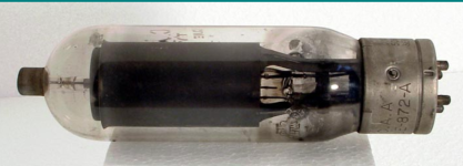
Type 872A is a half-wave mercury vapour HT rectifier, and is essentially an upsized type 866/A.​

Additional to the ratings given, the peak inverse anode voltage was 10 kV, and the peak cathode current was 5 Amps. A pair of these valves in a bi-phase circuit with an inductor input filter would deliver up to 7.5 kW (2.5 Amps DC @ 3000V), rather more than the normal load rating of many single-phase supplies. This, and the relatively high (5A) peak current rating imply that these valves are designed for use on 3-phase supplies.​

In such cases it is normal to use a set of 6 rectifiers to give '6-pulse' rectification because this provides a low level of HT ripple (about 5% RMS, easily smoothed) and a high power factor (around 90%).​

For the same PIV, 6-pulse rectification provides rather more output voltage than bi-phase rectification, ie. more power output per valve. A 'parallel' 6-valve rectifier bank would deliver up to 7.5 ADC at around 3300V (25 kW) and the same valves used in the (much commoner) '6-diode bridge' arrangement would provide half the current (3.75A) at twice the voltage (6600V), about right for a conventional 15 kW AM transmitter. Not bad for 37.5 W heating power and 15V forward voltage drop per valve!​


Of course, mercury rectifiers are notoriously delicate. To obtain long, trouble-free life it is essential to ensure very strict quality control during manufacture, to mount the valves upright in a temperature-controlled airflow, and to observe strict rules about pre-heating, RF screening, fault protection and overload protection. These are definitely professional valves.


Attachments

  • Screenshot 2024-12-22 at 14.29.38.png
    Screenshot 2024-12-22 at 14.29.38.png
    692.5 KB · Views: 46