Hi there,
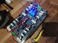
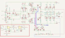
I am testing a PCB that I imported from China. But I have got mysterious biasing voltage!! I have tried to draw the basic diagram from the PCB. This board has more options, like speaker and thermal protection (UPC 1237), which is not drawn.
Left Side:
Driver Transistor (C4793) Base is 40mV and A1837 Base is 1.13mV
PNP (MJL21193) Base is 555 mV, and NPN (MJL21194) Base is 225 mV.
Right Side:
Driver Transistor (C4793) Base is 1.15V and A1837 Base is 60mV
PNP (MJL21193) Base is 0 mV, and NPN (MJL21194) Base is 555 mV.
Both the biasing transistor Vbe is 565 mV, and Vec is set to 1.35 V.
Is the VI limiter creating any instability?