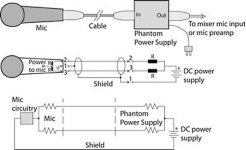
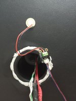
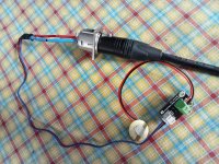
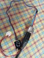
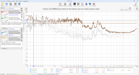
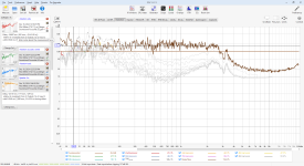
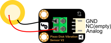
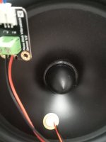
After more research, I built a cheap piezo accelerometer, first to see how it works, the first tests with rew and arta. It's very simple to connect to the audio interface, I used it on focusrite solo 3rd generation, use bostik adhesive, blutack for gluing the piezo disc, it sticks perfectly to any material. To see if the vibrations disappear, use wooden vises (clamps) in the most vulnerable points, i.e. right next to the bass, where the biggest vibrations are produced, it must be reinforced there. Here are the connection pins:
DFR0052 Focusrite Solo
OUT --------> Pin 2 (Hot)
GND --------> Pin 1 (gnd)
Pin 3 (Cold) - optional gnd (Pin 1)
DFR0052 Focusrite Solo
OUT --------> Pin 2 (Hot)
GND --------> Pin 1 (gnd)
Pin 3 (Cold) - optional gnd (Pin 1)
Attachments
-
 20181219phantom1.jpg25.2 KB · Views: 127
 -
 IMG20241218125155.jpg338.7 KB · Views: 120
 -
 IMG20241218125808.jpg716.5 KB · Views: 108
 -
 IMG20241218125824.jpg623.5 KB · Views: 101
 -
 IMG20241218125905.jpg418.7 KB · Views: 102
 -
 REW V5.31.3 12_18_2024 1_07_31 PM.png353.5 KB · Views: 99
 -
 REW V5.31.3 12_18_2024 1_45_03 PM.png785.9 KB · Views: 96
 -
 REW V5.31.3 12_18_2024 1_45_11 PM.png844.1 KB · Views: 92
 -
 REW V5.31.3 12_18_2024 1_45_40 PM.png337.9 KB · Views: 91
 -
 REW V5.31.3 12_18_2024 1_45_16 PM.png812.6 KB · Views: 86
 -
 REW V5.31.3 12_18_2024 1_45_44 PM.png338.8 KB · Views: 78
 -
 REW V5.31.3 12_18_2024 1_45_49 PM.png329 KB · Views: 77
 -
 Untitled - Arta 12_18_2024 1_46_30 PM.png102.4 KB · Views: 79
 -
 VibrationSensorSKUDFR0052_pin.png32.7 KB · Views: 104

I could find no documentation on the interface PCB. The Amazon listing shows a 5V supply. However a piezo transducer does not need power. There may be an amplifier on the little PCB but without info who knows? At least they are cheap to play with. if there is enough interest I could get a set and calibrate them.
Documentation is confusing. I assume it means no external power supply is needed when used with the three pin header that supplies power from the single board computer. So power is required.
- Supply Voltage: 3.3V to 5V
- Current: less than 1mA
I presume the components are for interfacing with an Arduino. For connection to a High Z mike preamp none of that is necessary. Connection to the usual low Z mike input will reduce the output a lot.
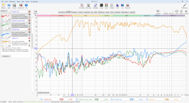
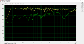
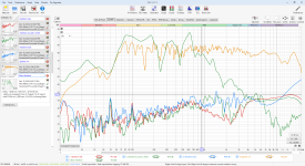
So what I noticed, I measured the microphone input voltage, it is 2.99v with phantom power on, when I turn it off it measures better, on the multimeter it has no voltage, but the measurements are more sensitive. here a measurement directly on the bass with phantom power off. I guess it behaves like a dynamic microphone that doesn't need phantom power, green is the bass measurement.

Attachments
I suspect that this one is better, and it is a few euros more expensive, I will do more tests and I will come back with the final conclusions, now I have learned to calibrate it. here the better model: https://wiki.dfrobot.com/Gravity__Flexible_Piezo_Film_Vibration_Sensor_SKU__SEN0209
A piezo is passive, and basically a capacitor. It doesn't have much output oomph, and benefits from a high - really high! - impedance buffer on its output, according to my understanding.
See - https://www.instructables.com/Guitar-Contact-Microphone-Preamp/
See - https://www.instructables.com/Guitar-Contact-Microphone-Preamp/
Focusrite also has 1Meg input SE impedance option.
Piezo datasheet at https://www.dfrobot.com/product-399.html.
The Gravity pcb has a dual opamp (LM2904) and a comparator IC (LM293) on it. https://www.dfrobot.com/product-1568.html
Perhaps better to locate the piezo on the dust-cap, not the cone, to avoid the complication of cone modes.
Piezo datasheet at https://www.dfrobot.com/product-399.html.
The Gravity pcb has a dual opamp (LM2904) and a comparator IC (LM293) on it. https://www.dfrobot.com/product-1568.html
Perhaps better to locate the piezo on the dust-cap, not the cone, to avoid the complication of cone modes.
- Home
- Design & Build
- Equipment & Tools
- Cheap accelerometer diy for speaker vibrations