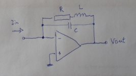
I calculated a simple R-L-C filter for correcting the sin(x)/x function droop that is present in zero-order-hold NOS DAC. It can be used with the common inverting operational amplifier topology. See the attached picture and Excel file.
Comments welcome.
Comments welcome.
Attachments
Yes - we love those reactive elements in the feedback loop instead of some phase and level linear, almost zero distorsion, no noise digital filters 🙂
Why listen to the original...
//
Why listen to the original...
//
Last edited:
Lcsaszar,
While it is possible to effectively combine the I/V circuit and the EQ function using a Multiple Feedback RC filter, I would keep those two circuits seperate for now in order to minimize design risk, and make it easier to troubleshoot should it not function correctly.
Assuming that you wish to stay with active circuits, follow the virtual ground I/V op-amp with a low-pass second-order op-amp based Multiple Feedback or Sallen-Key low filter. Both filters are RC only (no inductors), and can be easily made to produce the necessary response peaking (by selection of the RC values) to EQ the NOS treble droop. While also providing some analog reconstruction filtering.
Last edited:
Ken, I mostly agree with you. When converting my CD player to NOS I followed the radical approach and removed the SAA7220B/P chip altogether, along with the second order analog filter. Only the I/V converter (a single resistor in the feedback path of the opamp) remained in the analog section. A modestly peaking 2nd order RC filter looks like a good alternative, thanks for the suggestion.
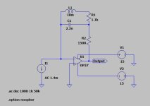
Hi lcsaszar - I've simmed this in LTSpice and it looks to be just as good a solution as the 2nd order peaking filter I've been using up until now. The only drawback I see is that the inductor won't be available in a small sized version (like 7mm diameter), it probably needs to be a Bourns RL181 type (10mm dia, 14mm tall). Which means it may not save space over a dual opamp S-K type.
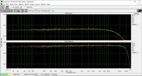
New NOS sin(x)/x droop correction. Upper (L) = no compensation, lower (R) = compensation. The circuit has +5 dB more gain than the standard 1.5k feedback. The inductor and the resistors should be of good quality, otherwise THD will increase. This is a quick and dirty solution, by adding only three components to an existing opamp I/V converter.
Attachments
Yes - we love those reactive elements in the feedback loop instead of some phase and level linear, almost zero distorsion, no noise digital filters 🙂
Why listen to the original...
//
Those digital filters often have no headroom for intersample overshoots, while analogue filters usually have enough headroom. Of course you can make a digital filter that has headroom, or digitally attenuate the signal before any filtering is done.

Not entirely sure NOS magic is only accounted for hf rolloff 🙂There goes your NOS magic. 🙂
What about phase?New NOS sin(x)/x droop correction. Upper (L) = no compensation, lower (R) = compensation. The circuit has +5 dB more gain than the standard 1.5k feedback. The inductor and the resistors should be of good quality, otherwise THD will increase. This is a quick and dirty solution, by adding only three components to an existing opamp I/V converter.
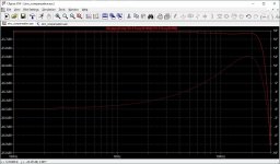
Are you suggesting that the 12 degree phase shift resulting from EQ is more of an issue than is correcting the FR droop? Or, am I missing your point about the phase shift?+12° at 18 kHz
Icsaszar was just answering Zoran's question. The deviation from linear phase is smaller.
- Home
- Source & Line
- Digital Line Level
- Sinc droop correction filter for NOS DAC