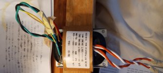
Bought a preamp board from Aliexpress along with transformer. When I hooked it up the transformer got very hot, so I disconnected it. Am I getting something wrong here or is the transformer defective? See pic of transformer. I hooked up the Green and Black wires as indicated to power .
Attachments
I can't make out what you have done there....
I would agree with black and green for 115 volt mains.
I would separate those secondaries (its weird having orange/orange as one winding and white/white as another because you can not identify phase).
With the power OFF measure the resistance of the orange/white leads and get them into two pairs that have continuity. According to the label that should be between orange and orange for one pair and white and white for the second pair. If you get continuity between orange and white then the label is wrong.
When you have got the pairs identified power it up and check it runs cools. Leave the secondaries floating. Measure the AC voltage across each pair and check its OK and what you expect. 15 volts as marked.
Now join any one wire of one pair to any one wire from the other pair and then measure the AC voltage between the two still unconnected leads. It should be twice the voltage of one pair you measured earlier as the windings are now in series. If you measure near zero then reverse the connections to just one pair and test again.
Assuming you get the correct total voltage now between the two free wires (so 30 volts AC) you should label them all. One of the free wires (either wire) is called 0 volt. Where they join the other wire of that pair is 15 volts and the other one left is labelled 0 volts. The other free end is 15 volts. So you have 0-15 and 0 -15 where the 15 and 0 in the middle are joined.
That gives you your 0-15 and 0-15 identifications.
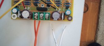
Apart the primary wires, did you try to parallel the secondaries? It seems like this looking at your picture.
If it is so I suspect you wired them out-of-phase, try and swap the white linked to the other orange and vice versa.
If it is so I suspect you wired them out-of-phase, try and swap the white linked to the other orange and vice versa.
I messed up something pretty obvious. I realize now that orange is one 15v output, and white the other 15v output. (I tried hooking up one channel and the transformer remained cool.) But now I am not sure how to wire both channels to the board. Where would the "negative" to the white channel go if there is only one ground to the board? Can it be connected to the orange "ground" already there? Please see pic. And thanks for all your help!
Attachments

- Home
- Amplifiers
- Power Supplies
- Transformer wiring for preamp