After months of research on Multiple Entry Horns, I’ve decided to build my own. While there are some excellent designs available, I’ve decided to design my own due to size constraints and budget limitations. My goal is to build a complete system for under €2000, including drivers, amplifiers, DSP, materials etc.
I’ll be documenting the journey and sharing the lessons I learn along the way. Since I’m new to this, I’d greatly appreciate any feedback or suggestions for improvement.
For those unfamiliar with Multiple Entry Horns (also known as Synergy or Unity Horns), I’ll include some resources below. In this post, I’ll refer to them as MEHs.
Why Synergy horns?
Synergy Calc V5
Synergy Patent
SynTripP: 2-way 2-part Virtual Single Point Source Horn | diyAudio
Scott Hinson’s MEH
The Design
Designing this project involved plenty of trial and error with drivers, designs, and Hornresp parameters. First I was going to build a 3-way MEH using four 4” drivers and two 10” drivers per horn + big subs using 15” drivers. However, when I discussed this with my better half, she wasn’t happy with the big size. So I changed it to a more compact design: 30x30cm 2-way MEHs paired with subwoofers.
For the 3-way MEH I got ideas and insights from Syn 9/Syn 10 and Cosynes, Scott Hinson’s MEH and SynTripPs. After deciding to go with a smaller horn, I began exploring more compact designs, such as: Two way synergy Horn, Portable Battery Powered MEH Build and others.
Size
Using Synergy Calc , I calculated the size and parameters for Hornresp. According to Bill Waslo: “with horns, bigger is better!”. While I would have preferred larger dimensions, I had to consider WAF, so I settled on a 30x30cm horn with an 80° coverage angle and horizontal pattern control to 850 Hz. After reading this discussion I changed the S1 value to 5.06 to match the CDs opening area to get a more precise Hornresp Simulation..

Drivers
Hornresp is a fantastic tool for modeling speakers, big thanks to David McBean for his contributions! After countless evenings testing various drivers and parameters, I settled on the following components:
Compression Driver - FaitalPRO HF108 (8Ω) I chose it because it works well in short horns and wide dispersion waveguides and people seem to like it a lot. The recommended crossover is 1300 Hz, which is what I’ll go with in my design.
Midrange - 2x FaitalPRO 4FE35 (8Ω) in parallel - they simulated well in Hornresp and have been used in some MEH builds before.
Hornresp parameters


3d printed horn
The inner section of the horn (shown in light grey in the 3D rendering) will be 3D-printed, while the outer flare will be constructed from 2 sheets of 19mm MDF with a dispersion angle of 130 degrees
The HF108 compression driver has a 31-degree exit angle, so the horn starts with a matching 31-degree angle and gradually transitions to an 80-degree angle at the midrange entry point.
To minimize unexpected cancellation notches, the inner corners of the horn are smoothed with 2mm rounded edges.


Mid driver Port location:
From Why Synergy horns?:
I’m crossing between the mid and the compression driver (CD) at 1300 Hz, which means the port holes for the mid drivers should be within 6.596 cm (calculated as 343/1300/4) of the CD’s exit.
I’ve been wondering if the critical distance is measured from the mid ports to the CD’s acoustic diaphragm or its exit. The CD’s exit seems to work well in previous designs posted here, so I decided to go with that. This approach also simplifies placement by allowing the ports to be positioned farther out.
To ensure I stayed within the critical distance, I decided to shorten L12 slightly (the distance between the CD’s exit and the plane of the mid-entry ports). L12 is 4.28 cm, meaning the centre of the mid-entry port is 5.84 cm from the centre of the CD’s exit, so it’s well within the required 6.596 cm for the crossover.
The circumference of the cross-sectional area at the tap-in point is calculated as 6.531*4=26.124, which is close to the wavelength of 1300 Hz.
However, when I model it in Hornresp, the cancellation notch appears well above 1300 Hz, and the mids start to roll off around 2000 Hz. I can increase the distances well above 6.6 cm before I get the cancelation notch near 1300 Hz. I’m not sure if I’ve missed something in my calculations and the measurements may differ when I measure the build speakers.
Mid driver Vrc:
I made the Vrc (closed rear chamber volume) fairly small 2 L in total (1L per driver). I still haven’t figured out how I will limit the chamber volume. Using tubes like those in the Cosynes would be challenging due to the distance between the mids and the compression driver.
Mid driver Vtc:
I didn’t feel like I needed to minimize the Vtc (throat chamber volume) as the mids can play high enough frequency already. Making it smaller using cone plugs seems more beneficial with bigger woofers (like on the SynTripPs) and also the B&C 4NDF34 which have been used in some designs. For now I’ve estimated 50cc per driver, but will measure the volume when I receive them. I might adjust the sizing after doing the final calculations with the correct volume.
Mid driver port size:
There are 2 entry ports per driver, 4 in total. The entry points are frustrumised, 2.76 cm in diameter closest to the driver and 1.95 on the inside of the horn, which translate to Ap1 of 24 cm² and Ap2 of 12 cm².
The ports are relatively small, with port velocity exceeding 17 m/s when played above 105 dB below 200 Hz. These are meant for home hi-fi use, so I don’t plan to play them too loud. I also don’t want to make them too big, so they affect the CD’s output. The ports are placed next to the corners to minimise the effect they have on the CD.
Vertical drivers:
This is something I haven’t seen mentioned often, and it seems to be overlooked in many MEH designs. I will place all the drivers vertically, on the side walls of the horn, to avoid driver sag.
Ported or sealed box:
While I was designing the 3-way MEH with 2x 10” woofers I tried modeling the low drivers in both ported and sealed box. I ended up choosing sealed after reading Arts comment from the SynTripP thread.
Subwoofers:
I haven’t decided on the subwoofers yet.
I’m considering adding two subs within the same enclosure as side-firing woofers in a push-push alignment. For example, two GRS 8SW-4HE drivers in a sealed configuration with a ca 42L volume. Here is a promising recommendation for these woofers.
If I go with this approach, I might decrease the vertical coverage angle of the MEH horn to 60 degrees to make space for the woofers below the horn. I guess it would be good idea to have the woofers close to the horn, within ¼ wavelength of the crossover frequency, but have also read that it doesn’t matter very much for frequencies below 100 Hz.
Adding the subs in the same enclosure would significantly increase the height of the enclosure, which may not pass the WAF. Alternatively, I could build a separate subwoofer placed approximately 1.5 meters away
Is it better to integrate side-firing subwoofers within the same enclosure or should I make a separate enclosure, which would need to be ca 1.5m away? I’d appreciate any feedback or suggestions on driver selection!

Amplifier and DSP:
As I don’t own any of the parts needed I have the opportunity to build the whole system from scratch.
The TPA3255/51 amps seem to offer great value for the money.
I’m looking into: Fosi ZA3, AIYIMA A70, Topping PA5 II and the upcoming 3e audio amps. I haven’t decided yet and would appreciate any recommendations.
Finding a DSP solution that fits the budget has been tricky. High-quality DSPs can be expensive, while the cheaper options often come with limitations.
I’ve decided to go with a Raspberry Pi 5 running CamillaDSP. For the DAC, I’ll start with the cheapest option: the AliExpress cards mentioned in this guide. RPi 5 Quad Stereo Sound with PCM5102A – Simple DIY Electronic Music Projects. User dptucunduva has had good results with it.
The reasons I chose it are:
It’s cheap and has good potential for upgrades. I can switch out the DAC module for a proper sound card like the Motu Ultralite mk5.
It’s a very flexible system, the Raspberry Pi can act as a streamer and allows for lots of add-ons like a remote controller, Those who use CamillaDSP seem very happy with it.
HiFiBerry DAC, which uses the same DAC chip seems to be decent according to the measurements here. I’m not expecting any fantastic results but see it as a cheap solution that has all the active crossover functions needed.
Next steps:
The CD and mid-drivers are on their way, and I plan to begin 3D printing the horn in early January. In the meantime I’ll focus on refining the horn design, adding mounting holes, figure out how to do the right vrc size. I also need to decide which amplifiers to use and start building the Raspberry Pi DSP. Additionally, I’ll work on designing the subwoofers and determining whether side-firing woofers are the best option.
Any suggestions or input would be greatly appreciated!
I’ll be documenting the journey and sharing the lessons I learn along the way. Since I’m new to this, I’d greatly appreciate any feedback or suggestions for improvement.
For those unfamiliar with Multiple Entry Horns (also known as Synergy or Unity Horns), I’ll include some resources below. In this post, I’ll refer to them as MEHs.
Why Synergy horns?
Synergy Calc V5
Synergy Patent
SynTripP: 2-way 2-part Virtual Single Point Source Horn | diyAudio
Scott Hinson’s MEH
The Design
Designing this project involved plenty of trial and error with drivers, designs, and Hornresp parameters. First I was going to build a 3-way MEH using four 4” drivers and two 10” drivers per horn + big subs using 15” drivers. However, when I discussed this with my better half, she wasn’t happy with the big size. So I changed it to a more compact design: 30x30cm 2-way MEHs paired with subwoofers.
For the 3-way MEH I got ideas and insights from Syn 9/Syn 10 and Cosynes, Scott Hinson’s MEH and SynTripPs. After deciding to go with a smaller horn, I began exploring more compact designs, such as: Two way synergy Horn, Portable Battery Powered MEH Build and others.
Size
Using Synergy Calc , I calculated the size and parameters for Hornresp. According to Bill Waslo: “with horns, bigger is better!”. While I would have preferred larger dimensions, I had to consider WAF, so I settled on a 30x30cm horn with an 80° coverage angle and horizontal pattern control to 850 Hz. After reading this discussion I changed the S1 value to 5.06 to match the CDs opening area to get a more precise Hornresp Simulation..
Drivers
Hornresp is a fantastic tool for modeling speakers, big thanks to David McBean for his contributions! After countless evenings testing various drivers and parameters, I settled on the following components:
Compression Driver - FaitalPRO HF108 (8Ω) I chose it because it works well in short horns and wide dispersion waveguides and people seem to like it a lot. The recommended crossover is 1300 Hz, which is what I’ll go with in my design.
Midrange - 2x FaitalPRO 4FE35 (8Ω) in parallel - they simulated well in Hornresp and have been used in some MEH builds before.
Hornresp parameters
3d printed horn
The inner section of the horn (shown in light grey in the 3D rendering) will be 3D-printed, while the outer flare will be constructed from 2 sheets of 19mm MDF with a dispersion angle of 130 degrees
The HF108 compression driver has a 31-degree exit angle, so the horn starts with a matching 31-degree angle and gradually transitions to an 80-degree angle at the midrange entry point.
To minimize unexpected cancellation notches, the inner corners of the horn are smoothed with 2mm rounded edges.
Mid driver Port location:
From Why Synergy horns?:
In a synergy horn we put the tweeter at the horn apex, easy enough, but how do we know where to tap in the midrange and bass drivers. We use the rule of 1/4 wavelength. So if we want to cross over from the midrange to the tweeter at 1200 Hz, we would have to tap in at 340/1200/4= 7 cm (2,8"). At the same time the cross sectional area (CSA) at the tap in point with in the horn. should be no bigger than in circumference, than the highest frequency being used in the bandpass. So at 1200 Hz the wavelength is 28,3 cm, so CSA can be no bigger than 28,3 cm, otherwise the hornwalls will no support the frequency. Same thing applies for the bass drivers. If we want to x-over from bass to midrange at 400 Hz, then the axial distance from the apex to tap in is 340/400/4= 21,2 cm (8,3"). This 1/4 wave rule makes sure that the drivers bandpass, is cut off and basically acoustically self terminate. What happens is that the frequency at play, for instance at 1200 Hz, travel toward the apex of the horn and then back again, but this time, 180 degrees out of phase, so a cancellation notch occur. In this way we can acoustically short circuit the bandpass, smart. What this cancellation notch will also do, is to acoustically lower the harmonic distortion above the cancellation notch. This effect can NOT be done electrically ONLY acoustically. This cancellation notch can be as big as -30 dB, so harmonic distortion is also lowered -30 dB. The result is a much cleaner sound, compared to other speaker designs.
I’m crossing between the mid and the compression driver (CD) at 1300 Hz, which means the port holes for the mid drivers should be within 6.596 cm (calculated as 343/1300/4) of the CD’s exit.
I’ve been wondering if the critical distance is measured from the mid ports to the CD’s acoustic diaphragm or its exit. The CD’s exit seems to work well in previous designs posted here, so I decided to go with that. This approach also simplifies placement by allowing the ports to be positioned farther out.
To ensure I stayed within the critical distance, I decided to shorten L12 slightly (the distance between the CD’s exit and the plane of the mid-entry ports). L12 is 4.28 cm, meaning the centre of the mid-entry port is 5.84 cm from the centre of the CD’s exit, so it’s well within the required 6.596 cm for the crossover.
The circumference of the cross-sectional area at the tap-in point is calculated as 6.531*4=26.124, which is close to the wavelength of 1300 Hz.
However, when I model it in Hornresp, the cancellation notch appears well above 1300 Hz, and the mids start to roll off around 2000 Hz. I can increase the distances well above 6.6 cm before I get the cancelation notch near 1300 Hz. I’m not sure if I’ve missed something in my calculations and the measurements may differ when I measure the build speakers.
Mid driver Vrc:
I made the Vrc (closed rear chamber volume) fairly small 2 L in total (1L per driver). I still haven’t figured out how I will limit the chamber volume. Using tubes like those in the Cosynes would be challenging due to the distance between the mids and the compression driver.
Mid driver Vtc:
I didn’t feel like I needed to minimize the Vtc (throat chamber volume) as the mids can play high enough frequency already. Making it smaller using cone plugs seems more beneficial with bigger woofers (like on the SynTripPs) and also the B&C 4NDF34 which have been used in some designs. For now I’ve estimated 50cc per driver, but will measure the volume when I receive them. I might adjust the sizing after doing the final calculations with the correct volume.
Mid driver port size:
There are 2 entry ports per driver, 4 in total. The entry points are frustrumised, 2.76 cm in diameter closest to the driver and 1.95 on the inside of the horn, which translate to Ap1 of 24 cm² and Ap2 of 12 cm².
The ports are relatively small, with port velocity exceeding 17 m/s when played above 105 dB below 200 Hz. These are meant for home hi-fi use, so I don’t plan to play them too loud. I also don’t want to make them too big, so they affect the CD’s output. The ports are placed next to the corners to minimise the effect they have on the CD.
Vertical drivers:
This is something I haven’t seen mentioned often, and it seems to be overlooked in many MEH designs. I will place all the drivers vertically, on the side walls of the horn, to avoid driver sag.
2. All drivers needed to be nearly vertical. The suspensions of a lot of home drivers will take a set over time if stored horizontal...I've seen it way too often. Since I'm using relatively inexpensive drivers I wanted to avoid this since I don't plan on building myself new speakers every 5 years or so. Source
Ported or sealed box:
While I was designing the 3-way MEH with 2x 10” woofers I tried modeling the low drivers in both ported and sealed box. I ended up choosing sealed after reading Arts comment from the SynTripP thread.
In retrospect, the 3dB gain the ports provide around Fb are probably not worth the -3dB 350 to 475 Hz and-10dB cancellation at 700 Hz. That upper cancellation requires more output from the HF driver to “fill the hole” in response they cause. Most 3" diaphragm drivers are already excursion challenged in the acoustical crossover range.
To sum up, don’t bother with cutting the port holes, leave the cabinet sealed 😉
Subwoofers:
I haven’t decided on the subwoofers yet.
I’m considering adding two subs within the same enclosure as side-firing woofers in a push-push alignment. For example, two GRS 8SW-4HE drivers in a sealed configuration with a ca 42L volume. Here is a promising recommendation for these woofers.
If I go with this approach, I might decrease the vertical coverage angle of the MEH horn to 60 degrees to make space for the woofers below the horn. I guess it would be good idea to have the woofers close to the horn, within ¼ wavelength of the crossover frequency, but have also read that it doesn’t matter very much for frequencies below 100 Hz.
Adding the subs in the same enclosure would significantly increase the height of the enclosure, which may not pass the WAF. Alternatively, I could build a separate subwoofer placed approximately 1.5 meters away
Is it better to integrate side-firing subwoofers within the same enclosure or should I make a separate enclosure, which would need to be ca 1.5m away? I’d appreciate any feedback or suggestions on driver selection!
Amplifier and DSP:
As I don’t own any of the parts needed I have the opportunity to build the whole system from scratch.
The TPA3255/51 amps seem to offer great value for the money.
I’m looking into: Fosi ZA3, AIYIMA A70, Topping PA5 II and the upcoming 3e audio amps. I haven’t decided yet and would appreciate any recommendations.
Finding a DSP solution that fits the budget has been tricky. High-quality DSPs can be expensive, while the cheaper options often come with limitations.
I’ve decided to go with a Raspberry Pi 5 running CamillaDSP. For the DAC, I’ll start with the cheapest option: the AliExpress cards mentioned in this guide. RPi 5 Quad Stereo Sound with PCM5102A – Simple DIY Electronic Music Projects. User dptucunduva has had good results with it.
The reasons I chose it are:
It’s cheap and has good potential for upgrades. I can switch out the DAC module for a proper sound card like the Motu Ultralite mk5.
It’s a very flexible system, the Raspberry Pi can act as a streamer and allows for lots of add-ons like a remote controller, Those who use CamillaDSP seem very happy with it.
HiFiBerry DAC, which uses the same DAC chip seems to be decent according to the measurements here. I’m not expecting any fantastic results but see it as a cheap solution that has all the active crossover functions needed.
Next steps:
The CD and mid-drivers are on their way, and I plan to begin 3D printing the horn in early January. In the meantime I’ll focus on refining the horn design, adding mounting holes, figure out how to do the right vrc size. I also need to decide which amplifiers to use and start building the Raspberry Pi DSP. Additionally, I’ll work on designing the subwoofers and determining whether side-firing woofers are the best option.
Any suggestions or input would be greatly appreciated!
Last edited:

I’ve been exploring the idea of side-firing 8” subwoofers.
I’ve sketched a design that fits the size requirements. The outer dimensions of the cabinet are 45 x 30 x 26 cm. The internal box volume is ca 15L, which is around 1/2 to 1/3 of the recommended box size for the subs.
As I understand it (please correct me if I’m wrong), it’s okay to make a sealed subwoofer smaller than the recommended size, but the sub will need more EQ and power to handle the lows. That shouldn’t be a big issue since I’ll be using an active crossover. The subwoofer requires 120W at 2 ohms to reach its Xmax at ca 30hz at ca 100 dB, so an amp like Fosi ZA3 should be able to drive them
At the moment, I’m considering the GRS 8SW-4HE-8 subwoofer but I am open to other suggestions.
Will this subwoofer implementation work or will it sound bad? Are there any other options I should consider for better results?

Here is the Hornresp simulation where the driver reaches xmax at ca 30hz, with some EQ and a low-pass filter:


I’ve sketched a design that fits the size requirements. The outer dimensions of the cabinet are 45 x 30 x 26 cm. The internal box volume is ca 15L, which is around 1/2 to 1/3 of the recommended box size for the subs.
As I understand it (please correct me if I’m wrong), it’s okay to make a sealed subwoofer smaller than the recommended size, but the sub will need more EQ and power to handle the lows. That shouldn’t be a big issue since I’ll be using an active crossover. The subwoofer requires 120W at 2 ohms to reach its Xmax at ca 30hz at ca 100 dB, so an amp like Fosi ZA3 should be able to drive them
At the moment, I’m considering the GRS 8SW-4HE-8 subwoofer but I am open to other suggestions.
Will this subwoofer implementation work or will it sound bad? Are there any other options I should consider for better results?
Here is the Hornresp simulation where the driver reaches xmax at ca 30hz, with some EQ and a low-pass filter:
The gradual transition will decrease the Fc compared to the usual conical expansion, but will limit the dispersion to the horn wall angle above around the wavelength of the transition length, making a "beamy" horn.The HF108 compression driver has a 31-degree exit angle, so the horn starts with a matching 31-degree angle and gradually transitions to an 80-degree angle at the midrange entry point.
Basically, the point you can visually see the center of the HF driver's throat is around the -6dB off axis point.
It should sound OK if you can keep the acoustical crossover at or below 200Hz, and the box is not too close to the room side walls.Will this subwoofer implementation work or will it sound bad? Are there any other options I should consider for better results?
At only 45 centimeters tall, the cabinets will require stands to get them up near ear-level.
I'd think you'd want to use the volume below to increase the enclosure volume, requiring less power to reach Xmax and lowering the box resonance.
Art
Nice project, and clearly you've been doing a lot of homework !
One high level observation...fwiw.
I think using just two 4fe35's is going to leave the design a bit out of balance. I think that is going to leave your mid range weak, and make it difficult to reach down to your subs adequately.
My vote would be to either use 4 of them, or size up to two 5"s or something.
(Also wouldn't worry at all about horizontal mounting or drivers this small. I don't think cone sag is a real issue until about 15" or greater.)
I know you're planning on lowish SPL...but even with that, I think just two of the 4" are going to disappoint...
With the tight cone clearance to the cavity filler a 2-way MEH requires, sag in horizontal 10" can (will..) be a problem long term.My vote would be to either use 4 of them, or size up to two 5"s or something.
(Also wouldn't worry at all about horizontal mounting or drivers this small. I don't think cone sag is a real issue until about 15" or greater.)
Considering the two 4" could play ~10 dB louder at 190 Hz than the 2x 8" at 30Hz, does not sound like it would disappoint.I know you're planning on lowish SPL...but even with that, I think just two of the 4" are going to disappoint...
I listened to my single one cubic foot MEH "boat horn" crossed at 165Hz using four 4” BC 4NDF34-8 with three 4x18" EV MTL-4 outdoors at 20meters away and it sounded OK.
That said, going to a pair of 5" would add around 4dB headroom, even at the same excursion as the 4FE345, and 5" can be had with a lot more excursion.
Art
Hi Art, maybe I'm confused, but I thought the only drivers that will be on the horn other than the CD, will be a pair of 4". I can't see sag being an issue with those, no matter how tight the filler. No?
Are any 10"s in play, other than potential sub drivers?
I've used both four 4fe35's and then switched to four 4NDf34's on the same syn horn. I think the 4fe35's did nearly as well as the B&C's. Good choice other than they are a pain to mount imo.
I do think only two of them is going to be weak, and make a thin spot in low mid.
Nice project, m-a. I started planning a 3-way MEH with HF108 and 4FE35 myself; it has been on hold for a while but I do intend to continue it in the comming year. I'm not experienced with MEHs, though like you have been doing syms and research, so will be watching your progress with great interest!
Yes, cones on horizontal drivers must sag a little initially, though this could be a small amount on small cones and might be accounted for in the design. Of more concern to me personally was that the sag can gradually creep/increase over time, especially if (as in my case) using bigger bass drivers on the horn too. But I realised if one makes the MEH symmetrical, one could periodically just turn the cabinet upside down to reverse or prevent any longer-term sagging.
As part of my own planning, I simulated a single 4fe35 as midrange in a MEH. In my situation (which may not be yours) the excursion chart showed it hitting x-max below about 150Hz:
limiting it to this maximum axoustical power:
However, I personally plan to cross the 4FE35s over at about 300hz so they would never see that excursion peak, and I could in theory play them much louder (assuming thermal limits or power compression don't interfere). Your situation my differ in crossover frequency if you have no bass drivers though; as you can see it is the lower frequencies where small cones need large xmax.
The reason your cone driver's reflected null might be at a higher frequency than expected could be because there are two different things going on with the distsances. There is of course the 1/4 wavelength driver spacing; either the acoustical centre of the compression driver or (for convenience) often its diaphragm location tend to be used by people for estimating that maximum distance. But the reflection of the midrange's sound (causing the null) is frequently said to come from around the apex of the horn, which is closer; some people use the compression driver's dust screen as an approximation though others have found it to effectively be in front of that.
Yes, subwoofer drivers can be put in a smaller sealed box if EQ and more power is available; it is slightly harder with bass reflex designs (IMO) because of the change in tuning and associated port length increases. But you'd want to check this didn't cause compromises from an amp beginning to struggle (or even clip) at the peaks, or the drivers starting to experience power compression; it is a law of diminishing returns, needing ever more power for small reductions in volume.
The opposing sub drivers are good for cancelling vibrations that might make the cabinet walk or transmit vibration to the floor. However also consider what side-firing woofers might mean with respect to speaker placement. If there are objects/furniture close by then a front-firing woofer might be more practical; it was for me.
It also isn't certain (or likely) that below the main speakers is the best place for subwoofers to be positioned; they will interact heavily with the room and its modes so some room locations will work much better than others. However, if you want to cross them over fairly high, they may indeed need to be close to the MEH in order to maintain seamless integration and even preservation of the stereo imaging. All designs are compromises, which we can't avoid and can only choose where to draw them, in this case it looks like crossing quite small MEH cones direct to subwoofers is one such. It could be fine, but if it starts to look difficult, possibly you might consider bigger cones for the two-way MEH (perhaps smaller versions of the SPL Runt, or Cask05/Chris A designs) or introducing bass driver(s) in some way. EDIT: it is fairly common to have bass drivers below the MEH (or in it), allowing subwoofers to be separate.
Just thoughts anyway, in case they're useful. Don't imagine that I'm any kind of MEH expert like some others here.
Last edited:
This is great. This is essentially the budget version of the Danley Sound Labs Signature HRE1.

You wrote "I don't think cone sag is a real issue until about 15" or greater", and suggested using drivers larger than 4".Hi Art, maybe I'm confused, but I thought the only drivers that will be on the horn other than the CD, will be a pair of 4". I can't see sag being an issue with those, no matter how tight the filler. No?
Are any 10"s in play, other than potential sub drivers?
The OP mentioned some inspirations including the SynTripP, using 10" drivers.
I've noticed at least 2mm cone sag on a lightweight 8" horizontally woofer, probably half it's Xmax.
Cone sag definitely was a problem on the upper EVDL10X 10" mid drivers used horizontally in Craig Hauber's EV MTH cabinets:
The sagging cone was torn after it hammered the phase plug.
https://forums.prosoundweb.com/index.php/topic,176835.0.html
Anyway, if enough clearance for Xlim is allowed for, cone destruction won't follow cone sag, but distortion will.
Art
First of all, thank you for the responses, I really appreciate the input! I’m a bit in awe getting feedback from all of you MEH experts.
Good point! A beamy horn might not be ideal. So I guess it's best to adjust the gradual transition to a conical one, the standard conical MEH horn seems like the best option.
In the previous design, the distance between the CD’s exit and the plane of the mid-entry ports (L12), is 4.28 cm. If I make it 2.55 cm, like the Synergy Spreadsheet suggests, then the horn has a constant angle of 80 degrees from the throat to the beginning of the 2nd flare. It’ll also have a gradual transition from circle to rectangle between the horn throat and S2 (mid-entry point plane).
My question is, will the transition from circular to rectangular over the entire 2.55 cm distance have any negative effect? Would it be better to make a shorter transition, similar to the throat adapter in the SynTripP (which I believe is 1/2")?
The cabinets are meant to be placed on a TV bench which is 68 cm tall. A floor-standing design would be much more ideal but then would go into the category of "big speakers" which my partner wouldn't be too happy about.
The nearest side wall is 1.6m away. And the tv bench is close to the wall behind the TV. Is this going to cause an issue?
Cone sag:
When I first started drafting this thread, I was researching for a 3-way MEH using four 4” drivers and two 10” drivers (+ external subwoofers). One of my main inspirations was mark100’s Syn 9, which has 10” drivers on the top and bottom walls. However, after reading about cone sag, I changed my design to use only vertical drivers, moving the 10” drivers to the sides of the horn.
That design ended up being too large, so I had to scale it down significantly and eliminate the 10” midbass drivers. I realized that cone sag wouldn’t be much less of an issue with the 4” drivers, but I still decided to include that part in this post.
Making the MEH smaller introduces quite a few compromises. The 3-way MEH I was working on before scaling down looked quite promising. It was efficient, with good frequency response between drivers, and capable of high output. Although it’d be fun to make, I realized they were way too much for my living room. When I started scaling down the design it was difficult to accept the compromises I’d have to make, so much so that I almost switched to doing a coax design, like Scott Hinson’s Coax Mini.
I had become a bit too obsessed with MEHs so the thought of giving up on MEH didn’t feel right. I decided to move forward with the smaller MEH, embrace the compromises and focus on creating a design that works within my constraints.
The 4 inch mids:
I was looking into both bigger drivers and 4x 4" drivers per horn but found out that 2x 4FE35 is plenty enough.
The main constraint is port size and the port location because of the high 1300hz crossover. Because of the ¼ wavelength rule, I can't move the mid-tap ports further out or I might get a cancellation notch in the mids below the crossover of 1300hz.
If I would go for mids with more cone area and xmax I’d also have to make the mid taps bigger, to compensate for increased port velocity.
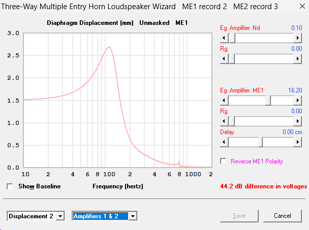
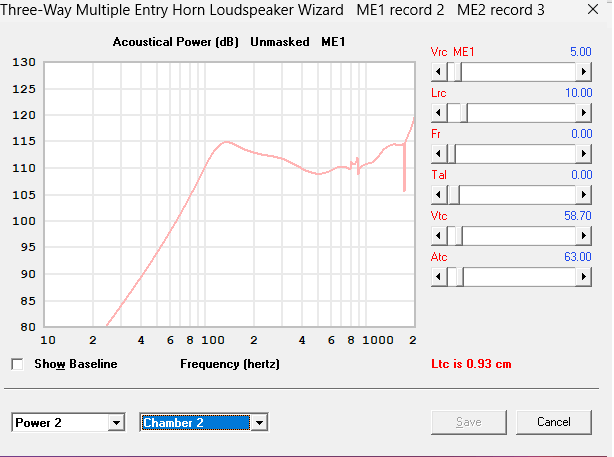
Here is hornresp sim with some EQ, highpass att 150hz and lowpass filter at 1300hz. SPL at around 103 dB, the port velocity at 17m/s, displacement at 1.8 (xmax is 2.7). This matches the sub output from the previous post pretty well.

If I increase the port area to 18mm I can reach xmax of 2.7 without exceeding 17m/s port velocity. However, that's pretty big and the circular ports take up almost all the space of the side walls. I could make the port elongated like the SynTripP and Scott Hinsons MEH, but not sure what I gain or loose by doing that.

the horn with 18mm port area

It might have been a better idea to get a compression driver that goes lower, like the classic BMS4550. Then I could have placed the ports further out on the horn, made them bigger and used bigger woofers that reach down to 100hz. I saw somewhere here that it’s possible to use the HF108 lower than the recommended crossover, even down to 800hz, but for the first prototype I want to try to make the crossover work at 1300hz.
At the end of the day I don't need the speakers to play loud. I actually prefer listening at quite low levels because I live in an apartment building and don't want to disturb the neighbours too much.
Writing this got me curious to do some more Hornresp sims. So I tried a quick sim with the 2x6FE100 placed further out the horn so it would crossover to CD like BMS4550 around 800hz. This is output at xmax and 17m/s mid tap port velocity. The question is, is this going to be any better? I still have chance to return the drivers and order different ones. Again this is for home hifi use so I don't need this much SPL.

The gradual transition will decrease the Fc compared to the usual conical expansion, but will limit the dispersion to the horn wall angle above around the wavelength of the transition length, making a "beamy" horn.
Basically, the point you can visually see the center of the HF driver's throat is around the -6dB off axis point.
Good point! A beamy horn might not be ideal. So I guess it's best to adjust the gradual transition to a conical one, the standard conical MEH horn seems like the best option.
In the previous design, the distance between the CD’s exit and the plane of the mid-entry ports (L12), is 4.28 cm. If I make it 2.55 cm, like the Synergy Spreadsheet suggests, then the horn has a constant angle of 80 degrees from the throat to the beginning of the 2nd flare. It’ll also have a gradual transition from circle to rectangle between the horn throat and S2 (mid-entry point plane).
My question is, will the transition from circular to rectangular over the entire 2.55 cm distance have any negative effect? Would it be better to make a shorter transition, similar to the throat adapter in the SynTripP (which I believe is 1/2")?
At only 45 centimeters tall, the cabinets will require stands to get them up near ear-level.
I'd think you'd want to use the volume below to increase the enclosure volume, requiring less power to reach Xmax and lowering the box resonance.
The cabinets are meant to be placed on a TV bench which is 68 cm tall. A floor-standing design would be much more ideal but then would go into the category of "big speakers" which my partner wouldn't be too happy about.
The nearest side wall is 1.6m away. And the tv bench is close to the wall behind the TV. Is this going to cause an issue?
Cone sag:
When I first started drafting this thread, I was researching for a 3-way MEH using four 4” drivers and two 10” drivers (+ external subwoofers). One of my main inspirations was mark100’s Syn 9, which has 10” drivers on the top and bottom walls. However, after reading about cone sag, I changed my design to use only vertical drivers, moving the 10” drivers to the sides of the horn.
That design ended up being too large, so I had to scale it down significantly and eliminate the 10” midbass drivers. I realized that cone sag wouldn’t be much less of an issue with the 4” drivers, but I still decided to include that part in this post.
Making the MEH smaller introduces quite a few compromises. The 3-way MEH I was working on before scaling down looked quite promising. It was efficient, with good frequency response between drivers, and capable of high output. Although it’d be fun to make, I realized they were way too much for my living room. When I started scaling down the design it was difficult to accept the compromises I’d have to make, so much so that I almost switched to doing a coax design, like Scott Hinson’s Coax Mini.
I had become a bit too obsessed with MEHs so the thought of giving up on MEH didn’t feel right. I decided to move forward with the smaller MEH, embrace the compromises and focus on creating a design that works within my constraints.
The 4 inch mids:
I was looking into both bigger drivers and 4x 4" drivers per horn but found out that 2x 4FE35 is plenty enough.
The main constraint is port size and the port location because of the high 1300hz crossover. Because of the ¼ wavelength rule, I can't move the mid-tap ports further out or I might get a cancellation notch in the mids below the crossover of 1300hz.
If I would go for mids with more cone area and xmax I’d also have to make the mid taps bigger, to compensate for increased port velocity.
Here is hornresp sim with some EQ, highpass att 150hz and lowpass filter at 1300hz. SPL at around 103 dB, the port velocity at 17m/s, displacement at 1.8 (xmax is 2.7). This matches the sub output from the previous post pretty well.
If I increase the port area to 18mm I can reach xmax of 2.7 without exceeding 17m/s port velocity. However, that's pretty big and the circular ports take up almost all the space of the side walls. I could make the port elongated like the SynTripP and Scott Hinsons MEH, but not sure what I gain or loose by doing that.
the horn with 18mm port area
It might have been a better idea to get a compression driver that goes lower, like the classic BMS4550. Then I could have placed the ports further out on the horn, made them bigger and used bigger woofers that reach down to 100hz. I saw somewhere here that it’s possible to use the HF108 lower than the recommended crossover, even down to 800hz, but for the first prototype I want to try to make the crossover work at 1300hz.
At the end of the day I don't need the speakers to play loud. I actually prefer listening at quite low levels because I live in an apartment building and don't want to disturb the neighbours too much.
Writing this got me curious to do some more Hornresp sims. So I tried a quick sim with the 2x6FE100 placed further out the horn so it would crossover to CD like BMS4550 around 800hz. This is output at xmax and 17m/s mid tap port velocity. The question is, is this going to be any better? I still have chance to return the drivers and order different ones. Again this is for home hifi use so I don't need this much SPL.
The HF108 can be crossed lower than 1300hz in many domestic situations, depending on the horn used and of course the SPL required. I personally feel it would be good in a 90x60 MEH down to at least 1khz or maybe somewhat lower (for my situation). So if there is any doubt, it could perhaps be worth double-checking that your 1300hz limit is truly valid for your situation.
IMO the BMS4550 doesn't seem much more capable than the HF108 in this respect anyway; it doesn't have a radically bigger Sd, for instance. Not compared to alternatives like the DCX464 coax, but which sadly are 4x the cost where I live.
IMO the BMS4550 doesn't seem much more capable than the HF108 in this respect anyway; it doesn't have a radically bigger Sd, for instance. Not compared to alternatives like the DCX464 coax, but which sadly are 4x the cost where I live.
Re the bigger cone drivers, I shall be interested to hear what the others say. If crossing a 2-way MEH to subwoofers, I'd personally favour bigger MEH cones of 6" or 8" (provided of course they have the characteristics needed to work well in a MEH, some bigger cones may gain nothing otherwise). This is going to be trickier to achieve than crossing the compression driver to small closer cones (the 1.3khz crossover you wanted becomes particularly more challenging; a rethink would probably be needed there), but more generally there are numerous examples of successful 2-way MEHs with bigger cones.
Alternatively my own preference would be to abandon the integrated subwoofer idea and instead use bass drivers - forward facing or in the horn. i.e. crossed higher than subs. The current MEH cone drivers could then remain small (and any additional subwoofers -if actually needed- could be placed more appropriately elsewhere).
Alternatively my own preference would be to abandon the integrated subwoofer idea and instead use bass drivers - forward facing or in the horn. i.e. crossed higher than subs. The current MEH cone drivers could then remain small (and any additional subwoofers -if actually needed- could be placed more appropriately elsewhere).
Last edited:
You wrote "I don't think cone sag is a real issue until about 15" or greater", and suggested using drivers larger than 4".
Yes, my goal was to help encourage @m-a to either:
use another pair of 4fe35's which may needed to be mounter on top and bottom horn sides (hence the don't worry about cone sag comment)
or use a pair of larger drivers in place of the current vertically mounted 4".
As far as cone sag in general, i just can't see being concerned until drivers get large.
I found a old technical paper once that described cone sag potential via T/S parameters. It sounded very plausible and my takeaway from it was until drivers get large with a relatively high mms, and relatively loose suspensions, there's no need for concern. I can't find the paper on any of old drives...if you or anyone has seen such, please post.
Also, I simply see too many speakers in the wild with horizontal mountings, with apparently no negative consequences.
All that said, for 12" drivers or less, if cone fillers could create an impact situation if cone sag ever did occur, I'd be more cautious.
But the way I'd solve the potential issue is increase cone filler clearance.
Being somewhat lazy, the 4fe35's or 4nd34's I use, have no cone filler, still reaching to 1000-1100Hz. Admittedly the coax CD's I use make that easy, but there are too many far less expensive CD's that will also reach to 1kHz to bother with cone filler on small mids, imo.
I have 8"s 10"s and 12"s all mounted horizontally...well, I should say 25-30 degrees off horizontal. I haven't noticed/heard any issues yet, but they are all only 5 years old or less.
Anyway, we all need to do what let's us rest easy... for me, I don't even think about cone sag for the drivers I've used, 12" or less.
Hi m-a, you've really put a lot of thought into your project. I'm impressed ! and wish i could use Hornresp for MEH's as well as you !
I guess part of the reason I haven't learned to model so well, is I can't help but question how well the model works given the experiments with I've made measuring port sizes and placements relative to cone centers....(which my maybe wrong understanding is that hornresp doesn't account for)
I've found low frequency extension increases the more centered a port is under the cone. HF doesn't seem to care so much, even when the port is out near the surround. Also, nothing has passed low freq as well as a single round port..
Anyway, on everything I've built, getting low freq extension has been the toughest part. And I suspect you'll find that too, despite the modeling.
I hope not though ! I hope your results inspire me to get deeper with Hornresp !
On last thought...I think there is are points when a MEH begins to lose its value, when SPL needs are relatively low, and when the benefit of pattern control being held to lower frequency diminishes due to a small horn size.
I think a conventional smaller coax starts to make more sense then.....ala Danley home stuff, KEF, Tannoy etc.
I might try something smaller in the ballpark of the BMS5CN140 or B&C 8CX21 sometime in the future.
Thanks for that cone sag paper...it or one very similar 'twas what I was looking for again
A conical horn is not the best option for uniform high frequency dispersion, but is easy to construct using plywood. Since you plan to 3d print, you don't need to limit the horn profile to a conical expansion.Good point! A beamy horn might not be ideal. So I guess it's best to adjust the gradual transition to a conical one, the standard conical MEH horn seems like the best option.
If the transition from circle to rectangle is only ~25.5mm, it probably won't "beam".My question is, will the transition from circular to rectangular over the entire 2.55 cm distance have any negative effect? Would it be better to make a shorter transition, similar to the throat adapter in the SynTripP (which I believe is 1/2")?
It would be easier to answer that if you could provide a picture of the throat transition.
My concern was if you planned to have the MEH below ear level, if you and your partner are OK with the placement, no issue for me!.The cabinets are meant to be placed on a TV bench which is 68 cm tall. A floor-standing design would be much more ideal but then would go into the category of "big speakers" which my partner wouldn't be too happy about.
The nearest side wall is 1.6m away. And the tv bench is close to the wall behind the TV. Is this going to cause an issue?
Note the "Calculating Driver Sag and Suitability for Vertical Mounting" paper formula Cowanaudio provided in post #17 would only apply to the date of installation, prior to the additional sag that occurs over time as the suspension is continually pulled downward.Cone sag:
When I first started drafting this thread, I was researching for a 3-way MEH using four 4” drivers and two 10” drivers (+ external subwoofers). One of my main inspirations was mark100’s Syn 9, which has 10” drivers on the top and bottom walls. However, after reading about cone sag, I changed my design to use only vertical drivers, moving the 10” drivers to the sides of the horn.
According to the formula, the EV DLX 10" woofer in post #10 would be "OK for horizontal mounting", yet it sagged ~4mm over time, near the same forward offset as it's Xmax.
Looks like those ports are overly large.Here is hornresp sim with some EQ, highpass att 150hz and lowpass filter at 1300hz. SPL at around 103 dB, the port velocity at 17m/s, displacement at 1.8 (xmax is 2.7).
If I increase the port area to 18mm I can reach xmax of 2.7 without exceeding 17m/s port velocity. However, that's pretty big and the circular ports take up almost all the space of the side walls
the horn with 18mm port area
View attachment 1395136
I don't think you need to worry about port velocity as much as their throat disturbance to the HF.
The photo below is the mounting used with the 4” B&C 4NDF34-8 (3.8mm Xmax, 5.7mm Xvar) in my "boat horn". No audible issues I would attribute to port velocity when driven to around Xvar.
If the re-entrant horns would have allowed a central port, I would have gone with it for the same reasons Mark mentioned in #16.
The BMS 4550's annular diaphragm does not have as much displacement as the HF108's 44mm dome diaphragm.It might have been a better idea to get a compression driver that goes lower, like the classic BMS4550. Then I could have placed the ports further out on the horn, made them bigger and used bigger woofers that reach down to 100hz. I saw somewhere here that it’s possible to use the HF108 lower than the recommended crossover, even down to 800hz, but for the first prototype I want to try to make the crossover work at 1300hz.
I'd expect the HF108 to have more clean output below 1000Hz and less IM distortion than the BMS 4550.
It's a trade off.So I tried a quick sim with the 2x6FE100 ...The question is, is this going to be any better? I still have chance to return the drivers and order different ones. Again this is for home hifi use so I don't need this much SPL.
The higher crossover the 4" would allow may sound slightly better and reduce IM distortion in the HF, while the 6" lower crossover would reduce IM distortion in the LF, but increase it in HF.
That said, with the SPL of your woofers being fairly low, I'd use what you have.
Art
Thanks for the excellent input! I now feel confident about my driver choices and will continue my experiments using the HF108 and 4FE35 drivers. Due to the crossover between the mids and subwoofer being higher than 100hz, I’ve decided to go with the side-firing subwoofer design (DSL HRE1 style).
I’ve made some changes to the design based on your suggestions. Now, there is only one midport per woofer, which I’m positioning as close to the center of the woofer as possible (woofer in blue on the picture below). I’ve stopped worrying about port velocity, so I made it smaller (8 cm² in total area). The port holes are now further away from each other, 90mm. I'm open to using a lower crossover than 1300hz, aiming for ca 1000hz.
The horn currently has an 85x75 dispersion, with a slightly lengthened L12—4.2 cm instead of the 3.68 cm recommended by the Synergy spreadsheet.
I feel like I still have so much to learn about horn design. I’m curious to explore ATH and ABEC AKABAK, but unfortunately, it doesn’t work with Wine on macOS, and I don’t have access to a Windows computer at the moment. Hornresp however, works fine with Wine on mac. I’m not sure what I’d gain by doing more work on the horn design, or if I should wing it, build the first test cabinet, and refine it from there.
I’m also working on the aesthetic side, adding a 4mm layer of mahogany plywood to the sides of the cabinet. The MDF and the 3D-printed horn will be painted, but I haven’t decided on the color yet.
- Home
- Loudspeakers
- Multi-Way
- 2-Way MEH build