Hi Guys,
I'm trying to build a phase splitter for a tube push pull amp, i only need about 2v p2p swing from this and I plan to run it off the negative bias supply, thus NPN rather than PNP. Any advice how I can improve this circuit? Priorities are PSRR, symmetry then distortion.
Cheers!

I'm trying to build a phase splitter for a tube push pull amp, i only need about 2v p2p swing from this and I plan to run it off the negative bias supply, thus NPN rather than PNP. Any advice how I can improve this circuit? Priorities are PSRR, symmetry then distortion.
Cheers!
I don't think 2vpp is enough to drive the output tubes.I'm trying to build a phase splitter for a tube push pull amp, i only need about 2v p2p swing from this and I plan to run it off the negative bias supply, thus NPN rather than PNP. Any advice how I can improve this circuit? Priorities are PSRR, symmetry then distortion.

i only need about 2v p2p swing from this and I plan to run it off the negative bias supply, thus NPN rather than PNP.
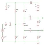
So should the sim have ground 'at the top' and your grounds points (D1,R9,C1) actually go to -24 volts. The input ground would have to be referenced to the upper true ground... or am I missing something? Would you not then use PNP's and flip it all around?
Unless you’re seeking the pleasure of designing your suggested circuit, how about a dual NE5532 opamp and a few resistors to implement the splitter?
I've played with phase splitter circuits. I discovered that it's a mistake to derive both phases from the same circuit because distortion in the two phases cancels each other in the feedback but not in the output. Best results come from an independent positive source and an inverter. I think you may need as much as 50V to drive output tubes.
I dont have split 15v railsUnless you’re seeking the pleasure of designing your suggested circuit, how about a dual NE5532 opamp and a few resistors to implement the splitter?
I figured i got this right way up, just have to swap the ground and 24vSo should the sim have ground 'at the top' and your grounds points (D1,R9,C1) actually go to -24 volts. The input ground would have to be referenced to the upper true ground... or am I missing something? Would you not then use PNP's and flip it all around?
don't like how the two outputs have very different impedances and often are not very symmetrical
If you’re interested in opamp implementation, consider above. You don’t need +/- 15 V supplies. -24V more than sufficient. I estimated the bias in your discrete design was about -6V, so I mimicked that target. But you could set bias divider to -12V by making both resistors 30k.
In any case, have fun with your project!
Given that DIY is about what you are interested in and not efficiency or performance, here are some suggestions. Note that the LTP only circuit is running on 50V because unlike the discrete op circuit, only a fraction of the supply is available as output. The op circuit example has 2x gain but that is optional.

Attachments
Wahab is correct. Use a single transistor in concertina configuration. This will split a 12AX7 and give a few ma of drive current as well. Use a 300v npn and you can drive anything tube
Given that BJT base current is not zero, there will be a slight difference in the amplitude of the two outputs. But you can tweak it by adjusting R7 or R2. This is not a problem with tubes or JFETs. A CFP would also improve the amplitude match and reduce the EF distortion.Long ago i used this to bridge some amps for PA usage, for good PSRR you ll have to replace the 1k resistance
by a cap multiplier using a BC547 FI + two resistances and a second low value cap.
- Home
- Amplifiers
- Solid State
- BJT Long tailed Pair as a phase splitter