Hello All,
Very much new to understanding this program.
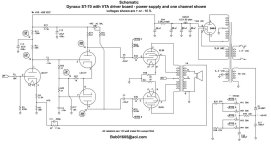
I'm trying to understand how to get loaded B+ measurements at output transformer with using the Vta st70 as a template. Mine is the same power supply section besides transformer to the Dynaco ST70 attached schematic.
transformer is 360VAC @350mA
output transformer is 4.5K
I'm running 6l6gc output tubes and 6ns7's on the driver board.
When loaded With a multimeter its got about 440vac at C1, 430vdc on the plates of 6l6 with 40mA bias and 375vac on the driver board B+ which is correct to the Octal schematic
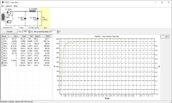
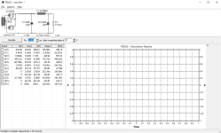
Attached is a screen shot what i have so far which seems like Ive done something wrong
So, Is the B+ voltage for output transformer read from the V(R1) RMS? C1 voltage isn't 440v
Help is much welcomed 🙂
Wayne
Very much new to understanding this program.
I'm trying to understand how to get loaded B+ measurements at output transformer with using the Vta st70 as a template. Mine is the same power supply section besides transformer to the Dynaco ST70 attached schematic.
transformer is 360VAC @350mA
output transformer is 4.5K
I'm running 6l6gc output tubes and 6ns7's on the driver board.
When loaded With a multimeter its got about 440vac at C1, 430vdc on the plates of 6l6 with 40mA bias and 375vac on the driver board B+ which is correct to the Octal schematic
Attached is a screen shot what i have so far which seems like Ive done something wrong
So, Is the B+ voltage for output transformer read from the V(R1) RMS? C1 voltage isn't 440v
Help is much welcomed 🙂
Wayne
Attachments
Did you set the current output for two channels? The power supply is for two channels. It looks like your simulation only draws enough current for one channel.
Hi,
Ohh yes Each output transformer is 4.5k.. so are you saying the R1 needs to be 9k instead of 4.5k?
Do you read of the Rms of max column in the results section?
Thanks
Ohh yes Each output transformer is 4.5k.. so are you saying the R1 needs to be 9k instead of 4.5k?
Do you read of the Rms of max column in the results section?
Thanks
Current through R1 = 461V / 4.5k ohms = 102 mA.
This would be the current used by one channel of the amplifier. If both channels of the amplifier are operating, the current will be approximately 205 mA. So, R1 should be adjusted so the current through it is approximately that value for the simulation (2.25k ohm).
You can also measure the voltage drop across the choke in the power supply when the amp is running (both channels) and calculate the current supplied by the power supply (V / 50 ohms). You can use this value for the simulation.
According to the schematic:
Therefore, dropping resistor = V / I = 55V / 25.0mA = 2.20k ohm
- each channel has 3 x 6SN7 which draws 4.2mA + 4.2mA + 4.1mA = 12.5mA
- total current for 2 channels = 2 x 12.5mA = 25.0mA
- B+ = 430V
- driver board voltage = 375V
- voltage to be dropped = 430V - 375V = 55V
Therefore, dropping resistor = V / I = 55V / 25.0mA = 2.20k ohm
Many thanks for the beak down.
I missed doubling the mA for the 6sn7' for both channels thanks
The thing i'm trying to figure out is how to add that to the PSUD chain. Would you add another C Filter section? 30u then the 2.2k?
I missed doubling the mA for the 6sn7' for both channels thanks
The thing i'm trying to figure out is how to add that to the PSUD chain. Would you add another C Filter section? 30u then the 2.2k?
With PSUD, there is a choice of resistor or current tap for drawing current. The current tap option is convenient as you do not have to modify the resistor value to get the current that you want. You can edit the load resistor and make it a current tap.
You can insert another RC filter section into the model to account for the 6SN7s. The result would be:
Rectifier - C filter - LC filter - 160mA current tap - RC filter - 25mA current tap
With PSUD, the final output load (resistor or current tap) is fixed. You can't add something after it, but you can insert before it. At least that's how my version works. So, to get to your final configuration, insert and edit until you get what you want.
Great!
I cant thank you enough pinholder, you have saved me alot of time. Sometimes its worth reaching out for help.
Wayne
I cant thank you enough pinholder, you have saved me alot of time. Sometimes its worth reaching out for help.
Wayne
Your doing very well to help too.🙂
It's my first attempt at building from scratch of a schematic rather that a pcb. Alot to take in but its enjoyable.
One more thing.. This is what I'm looking at building.. 6B4G mono block PP
I'm trying to work out how Pete got the 137mA at C2 on his schematic.
295v/5K=59mA then the plate current for each 6SN7's is where I'm getting confused. Is 2 plates and 2 currents wrong or right?
Attachments
From the schematic, the two 6B4Gs draw 60mA each for 120mA. The 6SN7s draw 3.6mA + 4.5mA + 12mA = 20.1mA.
So, total current = 120mA + 20.1mA = 140mA
Looking at the voltage drop across the power supply choke: dV = 310V - 295V = 15V
The Hammond 159Q DC resistance is approximately 100 ohms.
So current through the choke, I = 15V / 100 ohms = 0.15A = 150mA
This is in line with the currents through the tubes as noted on the schematic.
I did a couple of quick calculations to check the voltages and currents on the schematic and it looks like the current of 4.5mA through the the second triode of V4 (6SN7) is incorrect.
This was checked by calculating the current through the plate resistor, R3, and cathode resistor R15:
Current through R3 = (250V -172V) / 10kOhm = 7.8mA
Current through R15 = 76V / 10kOhm = 7.6mA
So, the current through triode 2 of V4 is around 7.7mA, not 4.5mA, a small change to the overall current.
- Home
- Amplifiers
- Power Supplies
- Help needed with understanding PSUD2