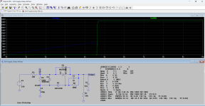
Maybe you could roughly model it by cross-coupling an NPN and a PNP and put two resistors between bases and emitters to get about the right trigger and hold currents.
anode to PNP emitter
PNP base to NPN collector
gate to NPN base and to PNP collector
cathode to NPN emitter
resistor between NPN base and emitter
resistor between PNP base and emitter
Maybe you need to put yet another resistor in series with the gate to ensure you cannot turn off the thyristor via its gate.
All right Marcel, thanks for your idea. Will give this circuit configuration a try. Have to experiment what types of transistors
I need to use to close-resemble the scr type. Will study some text books about scr's.
Joe.
I need to use to close-resemble the scr type. Will study some text books about scr's.
Joe.
I found SRC (etc) models at https://www.littelfuse.com/products/power-semiconductors/discrete-thyristors/scr.aspx and at http://www.bordodynov.ltwiki.org/
Note that this did not work until I changed the D3 to a Zener diode.
Note that this did not work until I changed the D3 to a Zener diode.
Attachments
Thanks steveu, as far as I know I did mean to configure d3 as a 100V zener diode.
Will use the model you gave in the schematic. Muchj appreciated!
Joe.
Will use the model you gave in the schematic. Muchj appreciated!
Joe.