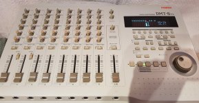
I have just bought a used Fostex DMT-8VL and it has a dead Channel, I am trying to find some advice about what could be causing this?
I don't know anything about repairing multitrack recorders or mixers, I bought this item thinking I was buying a fully working digital multitrack but it turned out to have a few problems which I think after a closer look were caused by liquid at some point in its life, I noticed that all the faders were rough and giving inconsistent audio from the input channels, and channel 8 was giving no audio at all, I stripped the whole recorder down and gave it some TLC all the faders have been thoroughly cleaned channels 1 to 7 are perfect with consistent audio all the way up the faders and they slide nice and smoothly now, the only issue it still has is the silent Input Channel 8.
What I have tested so far
If I turn the levels to their limits I can just about hear the audio from input 8 but its very faint, if I switch the L/R-Mon switch to Monitor I can hear the audio signal coming in from the channel 8 jack and I can raise lower the volume and pan the signal left and right using the pots in the monitor section but the fader, eq and meters have no effect when in this mode so I suspect that the problem is after the Monitor section?
I used input 1 to send and record the audio signal to Input Channel 8 and the Channel 8 Led Meter responded to the signal and recorded the track but I can hear nothing on playback the fader does nothing to the signal yet the meter for track 8 is peaking away showing that there is a recording there?
The recorded output from track 8 cannot be heard from the stereo outputs but it can be heard loud and clear from the rear direct out for Channel 8 so I am assuming that the recorded track bypasses the channel 8 fader section altogether?.
So I am stuck without any schematics or previous knowledge on mixer repairs, I am hoping someone can put me on the right track so to speak?
Thanks in advance
Dale
Attachments

i'd check the group assignment switch on channel 8
both contact cleaner and a visual inspection magnifying glass in hand for faulty/bad solders to the switch.
both contact cleaner and a visual inspection magnifying glass in hand for faulty/bad solders to the switch.
When you say group assignment switch do you mean input select switch, that is the only switch on channel 8 ?
Thanks, I think the diagram is from the DMT8 which was the first iteration of this multitrack, I did spray some contact cleaner into the Input/Track select switch but I am not getting even a crackle out of it, I will try the solder joints next as you mentioned.
Maybe. Some ecaps in the input string are couplers, others are part of the tone controls most mixers have.
I've fixed 3 mixers. Schematics are all about the same after op amps replaced transistors. You need a 1 vac detector, something like my Simpson 266-XLPM meter with 2 vac scale at 5000 ohms/volt. Cheap DVM will not work, AC scale is accurate only at 50 and 60 hz. RMS fluke meter might work, but at $180 it is a shame they cannot detect ultrasonic oscillation. My RA-88a disco mixer had such oscillation after I replaced the hissy 4558 op amps with 33078. Scope works but used ones are chock full of expired faulty electrolytic caps. Scope probes cost $50 up and are useless after stepped on. SImpson meter is 40 years old and no electrolytic caps in it to go bad. Sound probe designed for 1 vac signals can work too.
Then you look up the op amp IC diagram, usually on datasheetcatalog.com. Identify the inputs and output pins. You ground the negative probe of the meter at an input jack (naked phone plug) or the power supply ground, Then put a .047 cap series the red probe with clip leads or Pamona grabbers. Analog meters will show a result on the AC scale on DC voltages. DC voltage is usually not interesing. Be careful to not bridge an op amp output pin to the power supply pins with the probe. PS pins usually on the corners. Grabber is smaller and more precise than a naked meter probe. Use a lot of light and maybe reading glasses if you are over age 50.
You put a signal in the bad input. I use a transistor radio earphone jack, turned down to not exceed 1.5 vac. Rock stations will produce a beat that makes the needle dance to the beat, which proves you are not looking at inaudible ultrasonic oscillation.
Then trace the signal down from the top, to the bottom, then from left to right through the summing opamps, over to the output section. One unit had a bad via, a plated through hole that was not plated through. I stuck a wire through it, soldered both sides. Signal good to output op amp. I then dealt with the dodgy master volume control which I replaced.
Other possible problems, shorting tab of input or effect loop jacks not actually making contact. Oxidized switches, bad solder joints, wipers of various controls oxidized and not making contact. Punchdown blocks (numark) on ribbon cables can go open. Expired high ESR electrolytic caps.
Beware of surface mount parts. The air blast tool to replace those is ~$600, the paste solder is $15 an ounce. Through hole mixers are so much easier.
Note fostex has no reputation in my area. Possible some brands have controls (pots, jacks, switches) so cheap they are not worth fixing. I worked on Peavey units, which have a good rep. The Herald RA-88a was stupidly packaged (hummed with power transformer right next to 50x RIAA circuit) but had great controls (pots). An off brand graphic equalizer was not worth the $40 it cost me.
Happy hunting, and later performing with your band.
Last edited:
Indianajo went deep on how to suss out your troubles.
i'm uncertain as to how to advise you next as i don't know your troubleshooting skills, knowledge or equipment.
There were two of these Fostex multitracks the first one was the DMT8 and then came the DMT-8VL, this for me was a cheap ebay pickup $35, have not spent anything else on it and really would like the dead channel problem to be a cheap fix, I can solder no problem, have experience with SMD soldering, replaced half a dozen Korg MS2000 DSP chips over last few years and other micro soldering work all as a hobby, I have a good soldering iron, together with a Trinocular Microscope, the Fostex fader/ eq board is all through hole so pretty easy compared to SMD, was just hoping for someone with mixer fault experience to point me in the right direction, the DMT8VL also has a lower circuit board mounted under the Fader / eq board, all of the audio signals go to this board via several wiring looms, lots of SMD components on this board as well.
Attachments
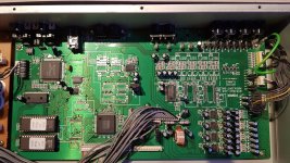
This is probably a USB interface mixer. All those digital parts like the 64703, probably a CPU. Hope there is nothing wrong with that. I could live without USB interface.
There is nothing so powerful as tracing the music through the circuit. With analog VOM (cheap $15-50) sound probe (diy) or scope (expensive and short lived). I tend to chop the problem in half, with "does work" " does not work" points far apart, then pull the end points together with further probing. I use the op amp legs as test points since those are are pretty obvious and standardized. But if the music disappears between say, the tone control op amp and the lower channel gain op amp, I have to look closely at the resistors capacitors and particularly pots to see exactly where the music is blocked. With master & monitor sends individually controlled on each channel, there is a monitor op amp in the chain too. Flow from top to bottom usually in order of the pot names, then from left to right over to the master volume pot, monitor volume pot, tape pot, and the several line drivers for those outputs.
Op amps don't usually fail in a mixer. One quick test for op amps, with a dvm dc 20 v scale, in+, in- and out should all be the same DC voltage. Boogered jacks, soldering and broken lands & vias is more a problem in my experience. Sometimes a channel pot will be ittermittant in addition to the master, if one channel, say the vocalist, was moved a lot. Haven't run into that yet.
People on ebay pay a premium for Peavey, Alesis, Yamaha, Ampeg, something and Heath mixers. Even "for parts or repair". Must be a reason.
i'd signal trace post the channel fader to the the master summing bus it's either a bad cap or an op-amp...is there any DC at the fader?
heck i'd look for any DC at opamp inputs to see what's what.
heck i'd look for any DC at opamp inputs to see what's what.
There is no USB on this Multitrack Mixer its from circa 1995, it has DAT ins and out if you want a digital copy, everything else is analogue.
If I move the input channel 8 switch to Monitor I can hear the audio from the input jack of channel 8, but when I switch to the L/R position to play the track back and use the fader and eq pots there is no audio at all, I was able to record on Track 8 by sending the input signal of input channel 1 to channel 8 where it records but cannot be played back, the recoding can be heard if I plug into the direct out of channel 8 on the rear of the machine, but this is the only place I can hear what is on channel 8?
If I move the input channel 8 switch to Monitor I can hear the audio from the input jack of channel 8, but when I switch to the L/R position to play the track back and use the fader and eq pots there is no audio at all, I was able to record on Track 8 by sending the input signal of input channel 1 to channel 8 where it records but cannot be played back, the recoding can be heard if I plug into the direct out of channel 8 on the rear of the machine, but this is the only place I can hear what is on channel 8?
The opamp inputs, I am assuming you mean the caps near to the input channel 8 fader?i'd signal trace post the channel fader to the the master summing bus it's either a bad cap or an op-amp...is there any DC at the fader?
heck i'd look for any DC at opamp inputs to see what's what.
Attachments

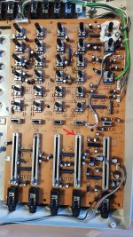
no you would have to be on the foil side of the board right at the IC pins, so just what is being used here for opamps?(they look like inline duals)
i was just looking at a magnified view of your board and some of the residue was reminiscent of past repairs involving "mixed drinks" spills, sugar and alcohol make crusty residue thats resistant to contact cleaner steam or hot water are the only cure there.

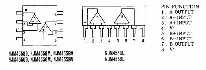
You did not report the part # on the op amps and did not download the datasheet as instructed. I see SIP packages I think. Here is the pinout for 4558, the op amp I know in SIP. Ins are 2,3 for amp one and 5,6 for amp 2. A real piece of obsolete garbage. Don't try to record a dynamic mike like a SM58 with 4558, hissy at high gain.The opamp inputs, I am assuming you mean the caps near to the input channel 8 fader?
Monitor out and main out are different busses. So apparently you are having trouble with main out. I don't know what L/R switch means and what output it affects. Headphone maybe? Headphone drive comes from the main chain in my PV8. BTW op amps in PV8 are NJM4562. Wait, there is hope for this mixer. NJM4562 come in SIP also. Look to see if this mixer is hideously obsolete (4558) or up to date (NJM4562). Note NJM4562 is a totally different part than LM4562.
As far as using the resistors and caps as probe points, their position is random depending on the routing software. I probe op amps or pots first as their position follows the block diagram. If there is a problem between one op amp and the next, then I will get out my reading glasses and follow the traces to the individual resistors or caps. Those round ends of the traces with no part leg are plated through holes that are supposed to route the signal from one side of the board to the other. Unplated hole was the problem both in one PV8, also the Samsung TV that could not see the remote IR input after a year.
There should be a block diagram in the user manual for this mixer. Amp stages are little triangles. That tells you the way the music is supposed to flow.
I don't see the crusty residue, but if you have any, hope you have a steam cleaner. We used to steam clean single board computers in the factory I worked at. Very dirty shop floor. Cleaned twice a year by blowing all the dust on the surfaces up in the room with compressed air. Ha! Take that intel.
Attachments
Last edited:
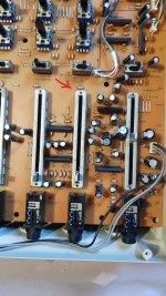
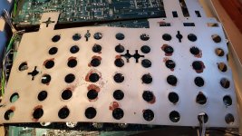
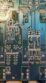
Yes the device has definitely had liquid inside it at some point, the anti interference shield under the pots showed clear signs of this, the other photo is of the rear of the Channel 8, the blue arrow showing the switch, I am just wondering if I could solder a jumper on this to bypass any residue inside the switch, this should prove your theory if I can get the audio to pass through I would know its a problem with the switch?
Attachments
You did not report the part # on the op amps and did not download the datasheet as instructed. I see SIP packages I think. Here is the pinout for 4558, the op amp I know in SIP. Ins are 2,3 for amp one and 5,6 for amp 2. A real piece of obsolete garbage. Don't try to record a dynamic mike like a SM58 with 4558, hissy at high gain.
Monitor out and main out are different busses. So apparently you are having trouble with main out. I don't know what L/R switch means and what output it affects. Headphone maybe? Headphone drive comes from the main chain in my PV8. BTW op amps in PV8 are NJM4562. Wait, there is hope for this mixer. NJM4562 come in SIP also. Look to see if this mixer is hideously obsolete (4558) or up to date (NJM4562). Note NJM4562 is a totally different part than LM4562.
As far as using the resistors and caps as probe points, their position is random depending on the routing software. I probe op amps or pots first as their position follows the block diagram. If there is a problem between one op amp and the next, then I will get out my reading glasses and follow the traces to the individual resistors or caps. Those round ends of the traces with no part leg are plated through holes that are supposed to route the signal from one side of the board to the other. Unplated hole was the problem both in one PV8, also the Samsung TV that could not see the remote IR input after a year.
There should be a block diagram in the user manual for this mixer. Amp stages are little triangles. That tells you the way the music is supposed to flow.
I don't see the crusty residue, but if you have any, hope you have a steam cleaner. We used to steam clean single board computers in the factory I worked at. Very dirty shop floor. Cleaned twice a year by blowing all the dust on the surfaces up in the room with compressed air. Ha! Take that intel.
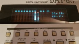
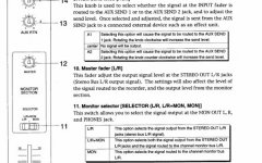
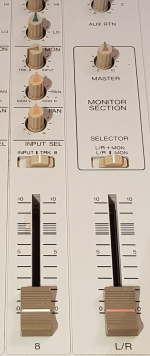
I have attached a screenshot from the DMT8VL Manual it shows the L/R switch as No11 moving this to the right to MON engages the Monitor section, I can hear the audio from the input jack on channel 8 here but not the recording on track 8, when I move this switch to the L/R position this allows me to playback, raise and lower the audio on all the other channels and use the EQ on each channel, but channel 8 does not respond at all?You did not report the part # on the op amps and did not download the datasheet as instructed. I see SIP packages I think. Here is the pinout for 4558, the op amp I know in SIP. Ins are 2,3 for amp one and 5,6 for amp 2. A real piece of obsolete garbage. Don't try to record a dynamic mike like a SM58 with 4558, hissy at high gain.
Monitor out and main out are different busses. So apparently you are having trouble with main out. I don't know what L/R switch means and what output it affects. Headphone maybe? Headphone drive comes from the main chain in my PV8. BTW op amps in PV8 are NJM4562. Wait, there is hope for this mixer. NJM4562 come in SIP also. Look to see if this mixer is hideously obsolete (4558) or up to date (NJM4562). Note NJM4562 is a totally different part than LM4562.
As far as using the resistors and caps as probe points, their position is random depending on the routing software. I probe op amps or pots first as their position follows the block diagram. If there is a problem between one op amp and the next, then I will get out my reading glasses and follow the traces to the individual resistors or caps. Those round ends of the traces with no part leg are plated through holes that are supposed to route the signal from one side of the board to the other. Unplated hole was the problem both in one PV8, also the Samsung TV that could not see the remote IR input after a year.
There should be a block diagram in the user manual for this mixer. Amp stages are little triangles. That tells you the way the music is supposed to flow.
I don't see the crusty residue, but if you have any, hope you have a steam cleaner. We used to steam clean single board computers in the factory I worked at. Very dirty shop floor. Cleaned twice a year by blowing all the dust on the surfaces up in the room with compressed air. Ha! Take that intel.
Attachments
- Home
- Live Sound
- PA Systems
- Fostex DMT-8VL Mixer Channel dead?