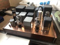
Phono LCR preamplifier
Designed by Sakuma, built entirely with Tamura transformers.
Has the ability to adjust the RIAA curve in 3 settings, according to the source material or taste of the user.
Separate signal and power supply chassis
6SL7 on the input, 6SN7 transformer coupled on the output, tubes are DC powered
Power supply has AZ1 as a rectifier and about 200H of induction, for a quiet power supply
If you have any questions, feel free to ask!
SOLD
Attachments

Last edited:

Sorry to be technical but are you sure this is the schematic?
It only has 15Hy of inductors, (they won't do much as inductors rely on current to work and at a maximum of 15mA that is not enough to be effective).
An AZ1 must have no more than 60uF as the first smoothing capacitor, your schematic shows a pair of SS diodes and 200uF! Good luck with that.
It only has 15Hy of inductors, (they won't do much as inductors rely on current to work and at a maximum of 15mA that is not enough to be effective).
An AZ1 must have no more than 60uF as the first smoothing capacitor, your schematic shows a pair of SS diodes and 200uF! Good luck with that.
No worries, should have indeed be more specific: PSU is not from the schematic. Originally, in the design by Sakuma, rectification was with a SS rectifier, due to no available heater winding in the PT. Signal chassis is from the schematic. Have adjusted the original post!
The classic reason: too much stuff! I need some room on the shelves... I have some other exotic builds, including one built by Sakuma himself!
This 6SL7/ 6SN7 design is the more accessible design of them all, so it might interest somebody. It has the very rare Tamura VL-SS permalloy EQ modules, which is a great part of the overall sound quality.
This 6SL7/ 6SN7 design is the more accessible design of them all, so it might interest somebody. It has the very rare Tamura VL-SS permalloy EQ modules, which is a great part of the overall sound quality.
Attachments
I was a bit puzzled by the PS to begin with, that seems the wrong way to do full bridge rectifier with a center tap secondary! Looks like a drawing error.Sorry to be technical but are you sure this is the schematic?
It only has 15Hy of inductors, (they won't do much as inductors rely on current to work and at a maximum of 15mA that is not enough to be effective).
An AZ1 must have no more than 60uF as the first smoothing capacitor, your schematic shows a pair of SS diodes and 200uF! Good luck with that.
It's full wave rectification with 2 diodes and a center tap, what would be the error?I was a bit puzzled by the PS to begin with, that seems the wrong way to do full bridge rectifier with a center tap secondary! Looks like a drawing error.
PSU is now:
PTx - AZ1 - 2uf (WE) - 200H (Lundahl) - 16uf (PIO) - 4H - 200uf (Elna Cerafine) - bleeder resistor
Channels are decoupled by an additional LC stage
PTx - AZ1 - 2uf (WE) - 200H (Lundahl) - 16uf (PIO) - 4H - 200uf (Elna Cerafine) - bleeder resistor
Channels are decoupled by an additional LC stage