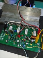
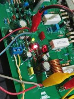
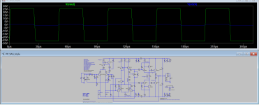
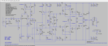
I am now embarking on a perilous journey on this DIY audio hobby. I am pushing the limits of my audio knowledge acquired here at DIYAudio. This project is an attempt to repurpose my pcb board intended for a CFP amp. LTSpice says the schematic will work, that is according to my understanding of how the circuit behaves.
The push pull VAS concept was taken from Keantoken's Aurum X amp with the output topology also being taken from Roender's FC-100 amp.
I ask you if anyone has made a similar design please comment your feedback. If this amp will turn out to be a firestarter 😄 I will not hesitate to toss the boards in the trash bin.
Thanks y'all!
Attachments

Last edited:
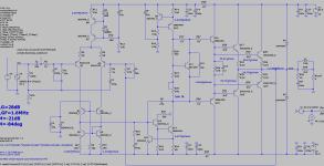
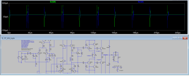
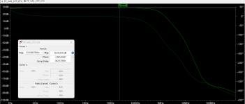
I have revised the schematic and it has now become EFII because it gives better result in the bode plot.
Question: Of all four cfp drivers only Q14 (upper npn) dissipates a little over 200mW, the rest are in the 160-180mW range. Do these four drivers goes also to the heatsink together with the bias generator and the outputs?
Thanks again!
Question: Of all four cfp drivers only Q14 (upper npn) dissipates a little over 200mW, the rest are in the 160-180mW range. Do these four drivers goes also to the heatsink together with the bias generator and the outputs?
Thanks again!
Attachments
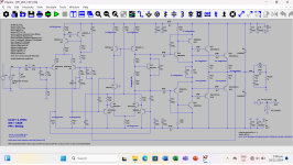
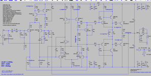
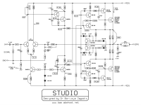
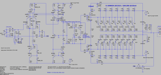
While scanning the FC-100 thread I found this rather interesting VBE multiplier made by member Bensen in response to thimios query. I was drawn into it upon seeing a similar scheme from the works of Valery and Dr. Bora Jagodic. Valery had the first transistor configured as diode and he used a Bryston like arrangement for the outputs while Dr. Bora had them arrange as limiter/protection (?) in his Studio amp and the output stage uses cascoded drivers.
It works in LTSpice, will it be sensible to adapt this cascode like vbe multiplier in this circuit of mine? or would it be best to use the standard one transistor VBE?
(PS, at the time of this posting I have yet to hear member Bensen's feedback)
Thanks!
(no worries all the risk goes to me 😅)
It works in LTSpice, will it be sensible to adapt this cascode like vbe multiplier in this circuit of mine? or would it be best to use the standard one transistor VBE?
(PS, at the time of this posting I have yet to hear member Bensen's feedback)
Thanks!
(no worries all the risk goes to me 😅)
Attachments
I am closing this project, I abandoned the idea so others may know if they happen to come across this thread while doing a search.
This project was superseded by another amp design. I named it Kaskoder cascoded front end 'blameless' type VAS EFII output stage. My thanks goes to Sir Wahab for his inputs. Kaskoder is by far my only project that came out to be flawless from simulation to the actual build, there is no need to adjust anything, it worked right away and surprisingly it was able to handle a bi-wired 3r bookshelf type speakers. 🙂
Albert