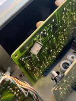
Hey all! I’m recapping my C200 that I acquired a couple of weeks ago. These boards are a pain to desolder components from, time consuming for sure. I’ve replaced half of all electrolytics as of today. Anyways, somebody has worked on it before me, fairly shoddy job. The PSU board has some components replaced with lifted pads as a result. See the absent solder pads on C5. C7 has also been replaced with a crappy brand of capacitor so that’s going out. Since the ”tech” that worked on this before doesn’t seem to have had a clue of what he was doing I got worried about the orientation of the cap. From what I’ve seen in various recap threads, and reading the schematic, the caps negative is supposed to go to anode on D7, and positive to cathode. Is that correct? It still works fine with the cap in this orientation, but I want to make it proper. For you people that knows more than me about schematics, what would the consequence be of having this cap in the wrong orientation? Could it have been installed with polarity reversed from factory by some reason? Thanks for any input!


To be sure, check the voltage across the capacitor for polarisation.
The possitive, should be on the anode of the diode, according to your circuit diagram. That of course, may be incorrect.
The possitive, should be on the anode of the diode, according to your circuit diagram. That of course, may be incorrect.

Thanks for that! Measured the voltage across the capacitor with positive lead to anode and got roughly -15 DCV. Which means the cap orientation is wrong, I take it?
Is that cap actually a polarised one? It looks physically big for a 33uF/40V Does it have + and - markings anywhere on it?
If it is polarised it looks reversed to me. The circuit shows emitter of Q3 as the most positive end. If you like proof just measure the voltage across the Zener and orient the cap with the same polarity as your red/black meter leads when they show a + voltage reading across the Zener.
Most electrolytics would fail leaky/short so given its working I suspect the cap fitted may be non polarised.
Hard to miss those 🙂Does it have + and - markings anywhere on it?
(as in across the whole cap, can't be made any more clear)
So it does 🙂
So according to the circuit it is in wrong way around. Measure to confirm and replace the cap. Do not reuse.
So according to the circuit it is in wrong way around. Measure to confirm and replace the cap. Do not reuse.
It is, but not drawn on the board layout. Most likely it has always been soldered that way but upon renewing it, the tech must have reversed the polarity. (On a blue Monday 🙂 )So according to the circuit it is in wrong way around.
- Home
- Amplifiers
- Solid State
- Accuphase C200 Recap Question