I have a Harmon Kardon AV-133 to repair ..
The driving transistor 2SD947F got broke while twisting the amp board from heatsink ,
While searching for equivalents I found BD139 and BD 679 to be very close alternatives.
But BD139 has 0.5A of less Collector current(Ic) when compared to orginal 2A,but has 190Mhz fT
While the BD679 has all specs good ,except the unknown transition frequency just mentioned as High .
Attaching the Datasheets ,hope someone would clarify.
Attachments
bd139 does not qualify since it’s not a darlingon configuration.
It’s possible that bd679 will work but be careful it’s not isolated like the 2sd947, since not shown, but it has exposed metal just like bd13x series
It’s possible that bd679 will work but be careful it’s not isolated like the 2sd947, since not shown, but it has exposed metal just like bd13x series
What is that transistor’s function? The built in base emitter resistors may be a problem in some applications. The ones in the BD are TOO LOW for use in vbe multipliers, but may be fine in a voltage regulator or small output stage.
Yeah, but it needs to be designed that way, with the Rbe in mind. If the original has a resistor an order of magnitude or two higher, and you dropped in lower values one probably would run out of adjustment range (on the low side) and not be able to get enough bias.
Shouldn’t be surprised if it requires re-engineering, though. BD139 would require more of it for sure.
Need to investigate= hifiengine or post the schematic for us to review.Harmon Kardon AV-133
Make your own darlingron based on the diagram on the data sheet 🙂
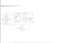
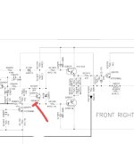
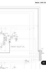
Attaching the Schematic as well as Service Manual (pg:39) belowNeed to investigate= hifiengine or post the schematic for us to review.
Make your own darlingron based on the diagram on the data sheet 🙂
There exist 5 2SD947F for the 5 pair of output transistor attached to heatsink
Attachments
Yeah, it is the Vbe transistor. I suspected so from the low voltage rating. You can’t just drop a power darlington with low internal Rbe values and expect it to work. And there isn’t even a bias pot, which means if you don’t get an EXACT replacement you will have to jack with it. I don’t even see anything close from Sanken anymore - and they made lots of audio types that only had the Rbe on the 2nd stage, and were several k ohms. Their stuff goes obsolete/NLA faster than anything I’ve ever seen in my life. A year ago they would have had a TO-220 that would have worked.
If you opt for a modern ST or Fairchild power switching type, get the lowest collector current rating available. That will push the resistor values higher, making them less of a problem. And R212, 213, and 214 would need to be lowered by an order of magnitude OR MORE. I would start with the values from that Electrocompaniet schematic. And it would need to be dialed in, preferably on the bench first. Then the exact components soldered in. Not just values, but the same ones. Measure the required bias voltage, collector to emitter on a working channel. Temporarily short the missing transistor to safely run the affected channel. Then construct the bias circuit on the bench, forcing 4 mA through it with a 9 volt battery and a pot. Adjust R212, 213 and 214 starting with those new values until you get the right voltage drop, down to 0.1 mV. Standard values, even 1% might be too much of a step between, so paralleling resistors with bigger ones is the best way to trim - short of using a pot. Jacking a pot into the circuit would work too, but making a good mechanical connection may or may not be possible. And if it comes loose in operation you’re in real trouble.
Personally, I would use a D40C1 or D40K1, insulate the tab, and re-route the leads with heat shrink over them. Then still have to trim the resistors, but only end up changing one. People often wonder why I waste time buying NOS and then go to the trouble to screen for fakes. This is why. I’ve got a good stash of those old darlingtons (including the PNPs), germanium, and low voltage high gain power types. There are older circuits out there where literally nothing else will work short of a full redesign.
Rather than messing with it, redesign, find a sub, etc maybe just take a shot at it and buy some new ones on the net.
I searched ebay, there are lots of sellers. Buy ones that have a pic, that matches the ones you have. Looks as if Rohm is the OEM, compare against datsheet. You can measure the new ones with the DMM in diode test mode to compare and determine if they are fakes.
On AK folks have done this method to save STV-4 diodes which do the same job as in, bias generator task
I searched ebay, there are lots of sellers. Buy ones that have a pic, that matches the ones you have. Looks as if Rohm is the OEM, compare against datsheet. You can measure the new ones with the DMM in diode test mode to compare and determine if they are fakes.
Show us a pic, it's possible to get at the leads again, dremel off the bottom plastic to expose the leads, attach new wires and call it a day 🙂The driving transistor 2SD947F got broke
On AK folks have done this method to save STV-4 diodes which do the same job as in, bias generator task
thats a lot of information for me , I would mess up not a pro like you yet 😌,Yeah, it is the Vbe transistor. I suspected so from the low voltage rating. You can’t just drop a power darlington with low internal Rbe values and expect it to work. And there isn’t even a bias pot, which means if you don’t get an EXACT replacement you will have to jack with it. I don’t even see anything close from Sanken anymore - and they made lots of audio types that only had the Rbe on the 2nd stage, and were several k ohms. Their stuff goes obsolete/NLA faster than anything I’ve ever seen in my life. A year ago they would have had a TO-220 that would have worked.
If you opt for a modern ST or Fairchild power switching type, get the lowest collector current rating available. That will push the resistor values higher, making them less of a problem. And R212, 213, and 214 would need to be lowered by an order of magnitude OR MORE. I would start with the values from that Electrocompaniet schematic. And it would need to be dialed in, preferably on the bench first. Then the exact components soldered in. Not just values, but the same ones. Measure the required bias voltage, collector to emitter on a working channel. Temporarily short the missing transistor to safely run the affected channel. Then construct the bias circuit on the bench, forcing 4 mA through it with a 9 volt battery and a pot. Adjust R212, 213 and 214 starting with those new values until you get the right voltage drop, down to 0.1 mV. Standard values, even 1% might be too much of a step between, so paralleling resistors with bigger ones is the best way to trim - short of using a pot. Jacking a pot into the circuit would work too, but making a good mechanical connection may or may not be possible. And if it comes loose in operation you’re in real trouble.
Personally, I would use a D40C1 or D40K1, insulate the tab, and re-route the leads with heat shrink over them. Then still have to trim the resistors, but only end up changing one. People often wonder why I waste time buying NOS and then go to the trouble to screen for fakes. This is why. I’ve got a good stash of those old darlingtons (including the PNPs), germanium, and low voltage high gain power types. There are older circuits out there where literally nothing else will work short of a full redesign.
I would try dremel ,as @rsavas sugeested and update here

Leads tacked back on where they broke off at the base of a package are just as likely to break off again as a pot tack-soldered to the top side of a surface-mount PCB.
Great. Another unobtainium Toshiba with no currently available derivative product. E-bay will be loaded up on fakes. Maybe somebody out there has some real ones, but my experience is anything out there that’s discontinued and people still want that rarely happens.
2SC3964 is a special part with very high hfe and not a darlington. So I guess you can use either one. Back to dremel tool fix. If you can manage, do not tack solder, try to use some thin wire and rap around the stub and even glue for extra strength
That could be why there are two series resistors (R212 and R213). To allow for factory adjustment darlington vs non darlington. If you do have a non darlington in there and the resistors are set appropriately, there are modern alternatives. You likely still want a 2 amp part with a gain of say 800 (to get the right vbe), but Diodes Inc makes things like that (for mosfet switching duty, and they sell them by the ton).
- Home
- Amplifiers
- Solid State
- Equivalents of 2SD947F