I'm hoping this gets someones attention. I still an unable to get right channel to come on. If anyone been following this fiasco then they don't need a recap, but for thoses who just checked in I will try to bring you up to date. A couple of weeks ago I decided to take my Krell KSA300-s out of a 3 year storage. This has been stored in a climate controlled building. I'm not the original owner, but I had used it for 5-6 years with no problem.
Anyway I got it set up and no right channel. No lights (led's for that side were on). Left side fine. So, I took it apart and found several issues with a previous repair. I fixed those and turned it on again, nothing. I decided to go in deep and found a couple of other problems so I fixed those.
To try and keep down the total times I took this apart I check every active component on that side. The only thing I haven't check were some timer ic's that appear to be used in the auto-bias circuit. Unfortunately the auto-bias circuit is the only thing I don't have a schematic for (and it appears no one else does outside of Krell who appears to be out of business).
I'm in the dark now and asking anyone that might have some insight to this problem to please come forward. I'm very close to putting it to the side and moving on. So, there you go.
I have attached some schematics that would be helpful.
Thanks,
John
Attachments
Did you check the power supply to that side?
Is there a voltage, if so, how much?
How much at the working side?
jan
Is there a voltage, if so, how much?
How much at the working side?
jan
On power up still no leds on the right channel. No power on that channel.
Did you check the power supply to that side?
Yes, basic informations are needed, rail voltages ok ?
Bias voltage Q37 Vce ?
I check every active component on that side
Check all resistors too even if they look nice, and check caps for shorts.
How about the cny-17?
Very useful would be a map of voltages on important points.
Power supply voltages correct. When powering on no bias lights are shown on the right side. When soft start is completed unit shuts down. Removed that side and left side functions fine. Voltages fine to right side when it is removed. All capacitors checked, all diodes, all transistors , all rectifiers. Here’s what I haven’t checked: not all resistors, no ic’s, and voltages on the board since it shuts down after slow start.
I did replace several cny-17’s. I’m returning to the unit today to check all resisters on that side. I’ve checked many, but will do a complete check today. Not sure about the ic’s since the section which has the most are associated with the auto-bias. Researching some of those are timers which most likely goes to the auto-bias for timing the auto-bias plateau.
So the whole amplifier shuts down.
Is there something like an error / protection LED on the front? If not, I would suspect the amp shuts down because either DC on the output or to high bias.
If the LED is there, I think the control circuits have a problem.
Is there something like an error / protection LED on the front? If not, I would suspect the amp shuts down because either DC on the output or to high bias.
If the LED is there, I think the control circuits have a problem.
I’m returning to the unit today to check all resisters on that side.
And best check small electrolytic caps in the control units too.
Well after changing out opto isolators and a few sketchy parts. I put everthing back together and while it did come on the led's on the right side didn't. I pulled the plug before any problems and checked all connections. Interestingly I drained the caps on the left side and when I tried to on the right and nothing. Could be I didn't have it on long enough. So I decided to turn it on again and when the full power was applied voltages look good (still no lights) on the right side. Then feeling the heatsink on the right side I realized the auto bias must not be working cause it was plenty hot. Before I could unplug the amp up comes some smoke from the output board.
Took it back apart and found Q29 died and the 5.6ohm resistor gone too. Q30 appears ok from initial test. Q29 and Q30 are BJT 8A 150V 36W NPN transistors. So I'm leaning towards the auto-bias circuit as being the problem. Any thought would be appreciated.
John
Took it back apart and found Q29 died and the 5.6ohm resistor gone too. Q30 appears ok from initial test. Q29 and Q30 are BJT 8A 150V 36W NPN transistors. So I'm leaning towards the auto-bias circuit as being the problem. Any thought would be appreciated.
John
I know of a very advanced and revolutionary technique for fault finding: measure voltage!
It's mind-boggling, not at all obvious but the courageous may want to give that a try.
It has advantages to eye-ball fault finding and random parts replacement.
The disadvantage is that you quickly find the problem so it cuts down on the pleasures of seeking.
But as said, it's quite advanced so isn't seen a lot. On this forum.
Jan

It's probably because you traveled into the future and were able to meet civilizations more advanced than ours and have access to technologies that have not yet been invented in our time.

I’m sorry you didn’t read my comments completely and have followers. I take no offense since until you read thoroughly you’ll never learn. As noted in my above comment “voltages looked good”.
If your advanced technique could minimize the smoke and trail of consuming parts then I would be interested or was your opinion all there is.
John
If your advanced technique could minimize the smoke and trail of consuming parts then I would be interested or was your opinion all there is.
John
So the whole amplifier shuts down.
Is there something like an error / protection LED on the front? If not, I would suspect the amp shuts down because either DC on the output or to high bias.
If the LED is there, I think the control circuits have a problem.
So it seems to be to high bias.
If the heatsink gets hot so fast, the bias must be extremely high.
Did you check transistors for shorts only or did you really make functional tests ?
The auto bias which could be defective, controls only a limited bias range imho.
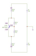
************ So, maybe the bias transistor Q37 is - open - and idle current becomes violent. *************
A simulation of the output stage incl. Q37 but without the unknown autobias could help.
Sim of bias network:
If Q37 goes open, bias voltage goes up to + / - 31V and over current protection will shut down the amp
Attachments
Last edited:
Thanks for the reply. The transistors were checked with a Peak transistor tester. I planned to do more testing but dedicating more time to the bias components
John
John
After fixing the damage you could try the following:
Bypass Q37 with a string of one or two 1N4003 diodes from C to E and see if the amp turns on. At your own risk 😎
Did you remove that transistor from the circuit for testing? Because there is less than 600 ohms across CE in circuit.
Bypass Q37 with a string of one or two 1N4003 diodes from C to E and see if the amp turns on. At your own risk 😎
The transistors were checked with a Peak transistor tester.
Did you remove that transistor from the circuit for testing? Because there is less than 600 ohms across CE in circuit.
- Home
- Amplifiers
- Solid State
- Krell KSA 300-S suicide watch