Hello,
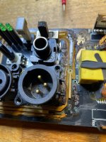
I've seen quite a few of these RCF active speakers but mostly with an issue in the SMPS - in one case the main SM controller, in the other an NPN buffering the signal from the 555.
The speakers I'm talking about seem to have exaclty the same layout, them being MK2 or MK4, with the same long black PCB.
In this case the power supply seems to work, I get seemingly all the voltages at the secondary (15V, -15V, 10V, -8V, 3.3V, 1.8V).
If I was to turn the power on I'd see the amber LED by the microcontroller turn on for a few seconds (possibly a sign of initialising) and then turn off. At that point all the LEDs at the back of the unit become lit (Status, Signal, Limit) and the speaker is silent.
There's a power off sensing circuit which I'm assuming is managed by the microcontroller, since the amber LED comes back on immediately after I turn off the power switch (before the supply rails start dropping), I can probe somewhere around the microcontroller a square wave with same frequency to the mains. This makes me exclude the microcontroller from the equation.
I've tested all SMD caps concerning the DSP and microcontroller area but couldn't find shorts.
I can't see any clock on the DSP MCLK pin, while there's a faint triangular wave on the adiacent OSCO pin, where the crystal connects.
The DSP is definitely getting power, though it doesn't seem to heat up or be running.
I'm not sure if anyone ever came across a schematic for these, it is pretty hard to trace those tracks on a black PCB.
How would you go around testing a class D amp in this case?
Alex
Thanks to the suggestion of a member of this forum you can find the schematic by looking for digpro 600b online, it should be easy to find.
I'm analysing the circuit in this moment and the first few things I notice are:
CSD is LOW (0V), from initial assessment is being pulled down from before R79, so from the DSP IC
I'm getting signal all the way to the top PWM controller, but not out of the second channel of the DSP IC
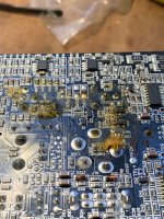
There's spots of brown glue in unusual places.
the yellow LED2 next to the PIC turns on for a few seconds and then turns off.
I'll post more updates as I find out more.
I'm analysing the circuit in this moment and the first few things I notice are:
CSD is LOW (0V), from initial assessment is being pulled down from before R79, so from the DSP IC
I'm getting signal all the way to the top PWM controller, but not out of the second channel of the DSP IC
There's spots of brown glue in unusual places.
the yellow LED2 next to the PIC turns on for a few seconds and then turns off.
I'll post more updates as I find out more.
I'm trying to understand how the ADAU1701 works, my assumption at the moment is that it's not properly loading the program from the EEPROM, therefore outputs a high level on all digital outputs. Therefore muting the PWM controllers through the CSD lines and lighting up all the statuts LEDs.
Still wondering though why it would be sending the input signal to only only two of the four outputs. Maybe it's partially corrupted?
Still wondering though why it would be sending the input signal to only only two of the four outputs. Maybe it's partially corrupted?
db technologie and RCF belong to the same company. That AMP module is used in a lot of speakers of db and RCF.
You find a schematics if you search for digipro 600b. It belongs to the first built versions of that module, but 98% did not change over the years.
You find a schematics if you search for digipro 600b. It belongs to the first built versions of that module, but 98% did not change over the years.
That brown glue problem is most likely causing your problem. It is conductive and corrosive.It is the main reason why those RCF modules do fail. Sometimes the woofer is silent sometimes the tweeter. You have to remove the brown glue from both sides of the PCB! And the best would be to remove it with a small drill (0,55/0,6mm )also from the vias. This really takes some time. The worst places are where the glue is dark brown and hard.This is in general on the side towards the big D-Amp coils. Maybe it changed its behavior over the time due to the heat. Most of those RCF modules are dying at the moment as this glue has been used for some years during production and now it has had enough time to damage things.
You can remove it with care with a small screwdriver and then clean the PCB with alcohol.
Then control the PCB for damaged connections.
Sometimes you can measure a too low resistance between CSD and ground due to the glue. It should be around 400k on a good module.
I will try to add some pictures later.
The CSD pins seem quite high impedance, and it sounds like it's the DSP driving them to ground through Q2/Q3. But it could be that the glue might be shorting something related to the DSP. At the moment I'm trying to figure out if it's loading the program from the eeprom at all.
Does that glue look like the brown offending one?
Does that glue look like the brown offending one?
Attachments

Did you check the VCC Voltage on PIN1 ? And then, did you check if you have 10V at Pin2 / CSD? On the front Panel only the green status LED should be on. Then you are sure that the DSP has loaded the programm and that it is running.
I find 10V on Pin1, on pin two I do get 0V but it seems because of the transistor shorting the pin to ground. When the unit is off I get high impedance to ground on that pin..
Thank you for sharing the pictures, I’ll reverse it and see how it looks!.
Thank you for sharing the pictures, I’ll reverse it and see how it looks!.
Status LED is green???
If the answer is yes check the Voltage @ R43and R79 to see if the DSP shuts down the AMP.
If the answer is yes check the Voltage @ R43and R79 to see if the DSP shuts down the AMP.
I'm not in front of the amp anymore but from what I remember there was something just under a volt at the base of Q2/Q3 which is probably enough to drive the transistor to conduction. On the other end of R43/R79 there is over 2 volts which comes from the SD CH from the DSP. It sounds to me the DSP is shutting down the amp. All LEDs come on after a second of powering up and stay lit, that is Power (named status on the front plate), Signal and Peak (green green red)
If all LEDs are premanent on you have a problem that the DSP does not start up correctly. They should be on for a short time, then all are off for a short time and then only the status should be on.
Sometimes the brown glue has an influence to C70 and C72. Simply try to re-solder those both SMD Capacitors may help due to the heat for some time. Anyhow I recommend to unsolder both and replace them.
Sometimes the programming gets corrupted due to problems with the clock. You may monitor the I2C with a digital scope or use a I2C sniffer.
it seems where the glue was brown it was fairly easy to scrape off, where it was more yellow it would get soft just using acetone. Anyway removing it didn't help, and can't notice much of a damage around vias and tracks underneath.
I haven't been able to replace C70/72 but they seem to measure fine on the ESR meter.
This is the sequence I have at start up:
All leds on (mute LED also on)
after a second or so the 3 panel LED off (and activity on I2C)
then mute LED comes off and 3 panel LED turn on (again activity on I2C)
that's the on condition, then if I power off the panel LEDs turn off and only seldomly the Mute LED comes on.
That makes me thing the Pic is active as it's sensing the AC input signal going dead and turning off the back LED (and sometimes turn on the MUTE led)
I've never "sniffed" I2C signals, do you think I'd be able to tell which kind of communication is happening? it sounds like the microcontroller should be master, then possibly reset the DSP after start up and the DSP then read the program from the eeprom.
The regions where the glue is dark brown and hard are the problematic ones. I remove it with a screwdriver taking care not to damage the PCB. Then I clean with alcohol. Aceton might be the hard way.
The I2C sequence:
First the DSP is master and loads its configuration from the EEprom. This is a big bulk of data and it might be easy to monitor that step with the scope.
Then after the the DSP is configured it is I2C slave providing the temperature of the two NTC's via I2C.
The PIC waits for a certain time after releasing the reset of the DSP. Then it is I"C master and queries the two temperatures cyclic from the DSP.
Unfortunately the DSP is not write protected. If something goes wrong data might be easily overwritten.
Loading the DSP data from the EEprom:
The DSP loads the first view bytes but stops loading the remaining ones if a magic number is not found.
If all three LED's on the frontpanel stay on and not only the status LED it is quite sure that the EEprom content got corrupted. Depending on the PIC FW version sometimes all 3 stay on or the red one is flashhing.
There some reasons why this may happen. One might be the master collision between PIC and DSP.
This might happen too, if the DSP clock is not stable. (Most likely due to the glue at C70/72), I have seen this already multiple times.
If you have a second module you can copy it by unsoldering the EEprom from the good one reading the content via something like a CH341a Programmer.
There are other ways, too. Sniffing the good one with a Raspberry PICO and programming with a Raspberry PI, ...
But it is very unlikely that it is something related to the PIC.
@Alexwfm did you have any luck repairing your amp? I acquired a pair of HD 12-A MK4's with the same or very similar amp. One amp turns on and works but with no highs (CD tested OK) and the other amp no lights at all. I'm not at your level of electronics troubleshooting so probably looking at either replacing the amps or converting the speakers to passive. Does anyone know where a replacement amp could be purchased, in the US preferable? I cant seem to find anything and other amps wont fit the narrow size. If I cant find anything I might just convert them to passive.
- Home
- Amplifiers
- Class D
- RCF ART710A MKII silent