Hi guys,
I'm designing a low noise linear regulated power supply for my phono preamp which is now using a cheap wall wart power supply.
I need 18v with 1A max and I'm going to use a Belleson SPX regulator.
What I like to know is how much filter capacitance do I really need. I'm thinking of using 4 2200uF capacitors as a filter capacitor bank. I think it will be more then enough, but does it make sense to use a larger capacitor bank? Or what is the advantage of using a capacitance multiplier (capmx) with smaller caps?
Transformer will be 18V/1.6A and the regulator is an 18V version.
Last edited:
Hi waltervn-
The transformer voltage is right on, 18V (RMS) will produce 25V peak, and assuming you are using a bridge rectifier you will have a filtered ~23V DC on the input of your regulator, so a good 5V headroom with which to work. The current rating on the transformer may be a little low if you really needed 1A for more than just brief moments. I can't really believe any kind of phono pre-amp is going to pull anywhere near that- (what topology is it? Do you have any idea what a typical draw would be) Are you indicating 1A because that is what the wall wart is rated at? Anyway, we'll go with the 1A.
Just wondering- why are you going to use a $40 fixed regulator? I understand not wanting to use the typical LM7818 fixed regulator, as I have heard it said that they do tend to be a little noisy. I have to trust this, I have never heard noise, as typically whatever you are powering also has filtering, power supply rejection, negative feedback, etc, so in general =any= kind of regulated supply is generally great, and far better then just the wall-wart (which is probably a switcher that is banging out LOTS of large ripple splashing across the entire audio range). If you DO want lower noise, please save a lot of money and use an LM317, or my preferred flavor of it, the LM338. It's a 40V 5A (if properly heatsinked) variable regulator that you can dial in with a trimmer or resistor adjustments for a wide range of output voltage, and they are very quiet. I really doubt the boutique regulator is going to improve in any noticeable way over the LM338- Of course they will say it will, but other than placebo effect I don't think you could tell in a blind test.
With a regulator, you really don't need as much filter capacitance as you think. The ripple coming off of the rectifiers is pretty low frequency compared to the bandwidth of the regulator, and as long as it has the voltage headroom to work with, the regulator will do a marvelous job of preventing ripple in the output with even a large ripple input. Let the regulator do the work as it is meant to, not the capacitors. The other concern is transformer heating. Everybody always forgets about transformer heating when they use huge capacitors here- The larger the bank of capacitors, the taller, and more narrow are the pulses of supply current from the transformer through the rectifier that charges the capacitors at the tippy top and bottom of the AC waveform. The transformer heating responds significantly to the height of these current pulses, so the larger the capacitor bank, the hotter the transformer. This is why transformers are often significantly over-spec'd in audio applications because an "impressive" amount of filter capacitance is confused with high quality or high performance and is a selling point on it's own.
There are plenty of online calculators to figure out how much capacitance you need. Having built a bunch of power supplies and worked on dozens more, I go more by gut feel these days based upon many many design examples that work well. For your 18V 1A application I would go with two of those 2200uF caps and call it good. You could probably even go with less and not have a problem. No need to worry about a capacitance multiplier. Keep it simple. Try to not put large amounts of capacitance on the output of the regulator- it really does not need that much - maybe 10uF to 100uF with a 100nF (104) in parallel. If you had any degree of reasonable performance with the switching wall wart, it was because the phono preamp probably had a pretty good amount of filter bypassing. With a regulated input of any kind I think you will be pretty happy.

Forgot to mention that the ripple coming out of the linear supply (and the switcher for the most part) is within the frequency range that any decent AC voltmeter can measure- Measure the RMS AC voltage coming out of the switcher at some point, and compare to the regulated output of your linear, while under load. I'm betting 50-200mV out of the switcher, and maybe a single digit number of milivolts from the regulator, most of which is probably induced in the meter leads. If I botched the filter capacitance value (or you still don't feel comfortable) measure the output ripple with your meter, again while under the actual load. (that's important) Try some more capacitance and measure again. If the input capacitance were too small, the regulator would be dropping out at the bottom of the droops and you would see a decrease in ripple with more capacitance.
Only true at switch-on/inrush while the caps are charging up, max 1/10 second.The other concern is transformer heating. Everybody always forgets about transformer heating when they use huge capacitors here- The larger the bank of capacitors, the taller, and more narrow are the pulses of supply current from the transformer through the rectifier that charges the capacitors at the tippy top and bottom of the AC waveform. The transformer heating responds significantly to the height of these current pulses, so the larger the capacitor bank, the hotter the transformer. This is why transformers are often significantly over-spec'd in audio applications because an "impressive" amount of filter capacitance is confused with high quality or high performance and is a selling point on it's own.
https://sound-au.com/articles/inrush.htm
Ok, it's on- "He's gettin' the book!"Only true at switch-on/inrush while the caps are charging up, max 1/10 second.
https://sound-au.com/articles/inrush.htm
I am a fan of Mr. Elliott, but in that article he is only addressing inrush, not transformer heating. BOTH are a problem with too much input filter capacitance, but designers these days tend to use rather large overspec'd bridge rectifiers that handle a lot of current, because they are inexpensive, and because they want to use rather large amounts of filter capacitance. I get it- ripple bad, more cap good- but transformer heating, is a concern that as I have said, often goes overlooked.
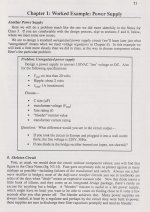
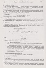
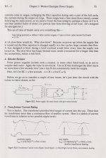
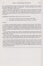
I would imagine the OP has probably fled the building having what he needs, but in case this is useful for him or others- I have scanned in four pertinent pages from the Student Manual for the Art Of Electronics by Horowitz and Hayes. In it they work through a design example of a 20V 1A max supply with ripple lower than 2V. This would be an excellent match for the OP's design, as he has 5V of headroom going into the regulator.
In it they recommend 4000uF of filter capacitance. My "gut" suggestion was pretty close.
They also have a bit to say about transformer heating:
Attachments
Right: Twice the caps, half the ripple! Any more is way above me, so Rod Elliot was all I could think of...
I appreciate you finding the source of that claim. I'm not following how the current went from 5A to 20A pulses...
I appreciate you finding the source of that claim. I'm not following how the current went from 5A to 20A pulses...
Narrower pulses to supply the same amount of charge => higher currents.
The 5A -> 20A was just by using larger filter capacitors, values not specified as it was only a rough (and probably extreme) example for illustration. The transformer does not charge the capacitance until the transformer voltage exceeds the capacitance voltage (plus diode drops). With larger amounts of ripple (capacitor discharges to a lower voltage through the half cycle) the transformer starts conducting current earlier in the cycle, and the pulse is shorter and fatter. With high capacitance the voltage has not dropped as far, so all of the conduction is compressed into a narrower, higher amplitude pulse. Since the power supply is delivering 1A current to the load under both situations, the same amount of net charge needs to be delivered by the transformer each half cycle, the only question is whether that net charge is delivered in longer lower pulses or shorter higher ones. Sorry if I over-explained that.
Also not mentioned is the fact that if too much filter capacitance is used and these pulses are narrow and of high amplitude, it can cause buzzing within the transformer that can resonate the cabinet, mechanical stress on the windings, the EM emitted from magnetic leakage and the conductors from the transformer to the filter capacitors is significantly higher and can couple, and there are other power loss components within the transformer that are exacerbated- eddy current IR losses, magnetic hysteresis, and many other smaller ones.
Also not mentioned is the fact that if too much filter capacitance is used and these pulses are narrow and of high amplitude, it can cause buzzing within the transformer that can resonate the cabinet, mechanical stress on the windings, the EM emitted from magnetic leakage and the conductors from the transformer to the filter capacitors is significantly higher and can couple, and there are other power loss components within the transformer that are exacerbated- eddy current IR losses, magnetic hysteresis, and many other smaller ones.
Can you throw a link out for that? I searched for awhile and could not find it. I would like to check that out.
That is Crazy?!!
That is Crazy?!!
I think the papers in post 5 is taking things to the extreme without quantifying everything, it supposes the transformer able to deliver 4 Amps at the very peaks of the sine wave. Apart from that, it is about the load, not the amount of capacitance.Right: Twice the caps, half the ripple! Any more is way above me, so Rod Elliot was all I could think of...
I appreciate you finding the source of that claim. I'm not following how the current went from 5A to 20A pulses...
The paper at sound.au is paragraph 5.3 ....figure 4 indicates current using different amounts of capacitance....
The paper is the linear power supply design subject on Elliotts pages.
It shows no apparent much peak higher current at normal circumstances versus capacitance amount.
This weekend, I tried for myself to see if there was much temperature rise when using a 2x30VAC transformer from a 2x50W class AB amp, bridge rectifier, 0.55A DC (40 Watts) offtake and 4700 uF caps.
the transformer temp rose about 10 degrees celcius the first hour and about 5 degrees again during 1.5 hours later, so it was already stabilizing a bit.
Then I connected 2x 33000uF caps extra, and monitored after an hour. Temp rise was around 1.2 degrees C during that additional hour, which is around what to be was expected anyway while the temperature stabilizing, even if the 33000 caps would not be there.
My example is about a ripple of 290 millivolts AC average on the DMM (around 800mV t/t on oscilloscope) versus 57 on DMM when the big 33000uF caps were added and 2 x 38VDC into 2x 69 Ohm power resistors.
The whole thing was to prove myself I should not worry about heating up a normal transformer used in the old amplifiers I "tinker", because those 33000 uF caps I have fit so nicely in certain amps I have having 10000 and 15000uF caps originally
In the end is my conclusion that if I would go from 4700 to 4700+33000 = 37700 microfarads in such normal amplifier, the transformer heatup in a real world situation is next to nothing according my little fluke 62 handheld indicator.
I had never heard of this fellow. He is engaging along with having an impressive bench! Glad to know about his work. Thanks to those who gave us the links.
Here it is:The paper at sound.au is paragraph 5.3 ....figure 4 indicates current using different amounts of capacitance....
The paper is the linear power supply design subject on Elliotts pages.
https://sound-au.com/power-supplies.htm#s53
5.3 Major Myth Regarding Capacitance
I only heard about this myth a couple of years ago (at the time of writing), and while I can imagine how it came about, it's completely bogus. Some people claim that as the capacitance is increased for a given sized transformer, the peak current is also increased. There are conflicting additional claims that the RMS input current to the transformer either A) does, or B) does not increase as well. Added to this is a further claim that the transformer will overheat because the current is higher.
In essence, this is all complete rubbish.
Hello
I take great pleasure in seeing that there are still people who appreciate the suggestions.
In your request of how much filter capacity a power supply must have, I will try to give my contribution. I can't tell you how much capacity, but I propose to consider a different approach to the solution of how to filter a power supply. The well-known ripple-eating circuits have appeared on this site and elsewhere before. There are many and of all types:
series and shunts
There are authors who have spent time and energy in constructive discussions, the works of Walt Jung, Salas, Keantoken come to mind, which you can find on this site. Do the research and you will free yourself from capacitors. As you may have understood, I hate capacitors, they take up space and cost a lot of money. Take a look.
Regards
Stefano
However, in an old magazine, where we former young people became passionate about electronics, there was a rule for calculating the filter capacity of a power supply and it was
C=20000/(Volts/Amperes)
This formula is quite reliable
C=20000/(Volts/Amperes)
This formula is quite reliable
Lets try that out. Say 50V supply at 5A: gices 2000µF. Lets assume conduction angle is 30 degrees and mains is 50Hz - filter caps get to discharge for 8.3ms every half-cycle. At 5A a 2000µF cap has a dV/dt of I/C = 5/0.002 = 2.5V per ms, so in 8.3ms that's a droop of 21V.
Doesn't look great. I'd expect more like 5V droop as a reasonable figure for a 50V supply, so 8000µF is more like it. Thus take the formula to be C (uF) = 80000/(volts/amps), [making the constant 0.08 farad-ohms, which is the same as 80ms] or put another way an RC time constant of the filter cap with the load resistance should be 80ms (an order of magnitude longer than the hold-up period the capacitor is supposed to supply current for), thus ensuring only 10% droop during that period.
The units of RC are seconds, therefore the farad is the same as seconds/ohm. (Likewise the henry is the same as ohm-seconds). Although strictly this only applies to constant current for capacitors and constant voltage for inductors I think.
Just as an easy to remember, rough rule-of-thumb type figure, I assume at least 1uF of capacitance per mA of load current will be needed.
So, if the load will draw 500mA, the capacitor will need be at least 500uF, and so forth.
So, if the load will draw 500mA, the capacitor will need be at least 500uF, and so forth.
The peak rectifier current does vary directly with the input filter capacitance, for a constant DC load current.
Examples: https://pressbooks.nscc.ca/semiconductor/chapter/rectification/
Examples: https://pressbooks.nscc.ca/semiconductor/chapter/rectification/
- Home
- Amplifiers
- Power Supplies
- Filter capacitors in phono preamp power supply