Hi, i am building a 350w +/-60v isolated SMPS. I recently finished a succesfull DC-DC converter, so this is my first time using a gate drive transformer to isolate the switching circuitry from the half bridge.
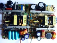
My first prototype (input rectifier and output caps + inductor on seperate board, no heatsinks yet):

The unregulated smps i have built is working pretty nice so far however i would love any improvements and suggestions with the circuit, but also i am a little stuck on what to do with the "proportional drive winding", that i will explain.

Highlighted in red from pins 5-2 of the GDT, is what i will call the "proportional winding" though this is probably the wrong terminology. Follow it along and you see that this winding going through the gdt actually links the main transformer(U1) to the half bridge! The reason for this winding through the GDT is to help the SMPS startup, by providing a little bump on one of the GDT gate drive secondaries, which is enough to start up the auxilary winding on U1 for the tl494, which quickly takes control over GDT.
I belive the "proportional winding" is also to help supply a bit of extra current to the GDT's secondaries to provide a little extra gate drive current.
The problem is, im not sure how many windings i should do for the proportional winding. Unfortuanately, this GDT transformer i bought has no data sheet, so i am unaware of how many windings there are for its gate drive secondaries. I had to hand wind the proportional winding onto the GDT, and at the moment i am using 3 turns. I could vary the number of proportional winding turns and take osc measurements, but i dont know what GDT output i should be aiming for.
GDT secondary drive winding oscilloscope measuement without any current flowing through the proportional winding (TL494 externally suplied):

GDT secondary drive winding osc measurement with the SMPS fully on, current flowing through U1 and proportional winding:

Drive circuitry on primary side of GDT, if of any help:

My first prototype (input rectifier and output caps + inductor on seperate board, no heatsinks yet):
The unregulated smps i have built is working pretty nice so far however i would love any improvements and suggestions with the circuit, but also i am a little stuck on what to do with the "proportional drive winding", that i will explain.
Highlighted in red from pins 5-2 of the GDT, is what i will call the "proportional winding" though this is probably the wrong terminology. Follow it along and you see that this winding going through the gdt actually links the main transformer(U1) to the half bridge! The reason for this winding through the GDT is to help the SMPS startup, by providing a little bump on one of the GDT gate drive secondaries, which is enough to start up the auxilary winding on U1 for the tl494, which quickly takes control over GDT.
I belive the "proportional winding" is also to help supply a bit of extra current to the GDT's secondaries to provide a little extra gate drive current.
The problem is, im not sure how many windings i should do for the proportional winding. Unfortuanately, this GDT transformer i bought has no data sheet, so i am unaware of how many windings there are for its gate drive secondaries. I had to hand wind the proportional winding onto the GDT, and at the moment i am using 3 turns. I could vary the number of proportional winding turns and take osc measurements, but i dont know what GDT output i should be aiming for.
GDT secondary drive winding oscilloscope measuement without any current flowing through the proportional winding (TL494 externally suplied):
GDT secondary drive winding osc measurement with the SMPS fully on, current flowing through U1 and proportional winding:
Drive circuitry on primary side of GDT, if of any help:
Last edited:
Doporučuji použít originální GTD z PC zdroje bez převíjení. Spojení mezi GTD a 13009 musí být co nejtěsnější, max 10mm, jinak to nebude dobře fungovat.
Červené vinutí je proudová zpětná vazba samooscilačního obvodu a TL494 pouze zpomaluje tento oscilátor zkratováním primární GTD a přidáváním mrtvých časů. Kondenzátory 1uF v základně 13009 jsou ve vašem schématu zapojeny obráceně.
Přidejte napěťovou a proudovou zpětnovazební smyčku a ochranu proti zkratu a podpětí podle obrázku.
Last edited:

Thank you, i cant believe i didnt see i had put my capacitors in wrong polarity, im suprised it didnt cause more issues.
It runs fine and puts out +\-80v. I still have not gotten around to adding feedback yet, its only my second prototype.
On startup the self oscillation is a bit bumpy, i can audibly hear the transformer tick for a second before the tl494 gets adequate power. I think the transistors should be able to handle a bit of abuse at startup.
Transformer has 19 + unused ct + 19 turns of 0.5x2 wire.
Secondary has 19+ct+19 of 0.8x1 wire.
I believe the core material is most likely pc40, but i am not certain.
I have tried to shorten the half bridge transistor gate line as much as possible, though it is difficult with the space of everything.
I think the ticking because of difficult startup is because the turns for the gdt proportional winding might be too little, im still not sure about it. I only have one turn for it.
The GTD transformer in the PC supply has 2 turns as the current winding. Use a GTD transformer disassembled from PC supply without rewinding.
And also add all the feedback like in the picture.
Power suppy use 4 tranformers 2x20V or 2x40V or 2x80V, all transformers without rewinding disasembled from PC In all cases.
And also add all the feedback like in the picture.
Power suppy use 4 tranformers 2x20V or 2x40V or 2x80V, all transformers without rewinding disasembled from PC In all cases.
Attachments
Last edited:
- Home
- Amplifiers
- Power Supplies
- GDT Proportional winding?