Hello all,
After noticing a very high temperature on my REGA mira 2000 (not possible to keep my hand on the lower casing after few hours), I started to check the idling current of the power amp stage.
It was a good check, because one channel was totally out of range (more than 50mV at power on). So I set both at 7,5mV (like it is described in this thread).
Since the idling current have been re-set, the amplifier is not hot at all. After few hours, it became barely warm (nothing compared to what was before!).
I think I fixed the issue.
This could have been the end of the story, but I had the chance to have during few days a thermal camera and I started to check the internal temperature of the amplifier.
The surprise was to see that the 4x power transistors stay cold, but some components are becoming very hot rapidly.
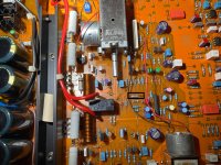
A little resistor (like 1/4w) is rising instantly up to 80°C. It is R88 named that you can see on the picture.
I am wondering if this is normal or not.
The resistor looks different from the other. It is a second hand amplifier that I bought in 2018.
Just to add that I never faced any "sound" issues with this amplifier. And it works few hours per day since 2018...
Any thought? Could be a normal behaviour of the amplifier ?
Thanks for reading !
After noticing a very high temperature on my REGA mira 2000 (not possible to keep my hand on the lower casing after few hours), I started to check the idling current of the power amp stage.
It was a good check, because one channel was totally out of range (more than 50mV at power on). So I set both at 7,5mV (like it is described in this thread).
Since the idling current have been re-set, the amplifier is not hot at all. After few hours, it became barely warm (nothing compared to what was before!).
I think I fixed the issue.
This could have been the end of the story, but I had the chance to have during few days a thermal camera and I started to check the internal temperature of the amplifier.
The surprise was to see that the 4x power transistors stay cold, but some components are becoming very hot rapidly.
A little resistor (like 1/4w) is rising instantly up to 80°C. It is R88 named that you can see on the picture.
I am wondering if this is normal or not.
The resistor looks different from the other. It is a second hand amplifier that I bought in 2018.
Just to add that I never faced any "sound" issues with this amplifier. And it works few hours per day since 2018...
Any thought? Could be a normal behaviour of the amplifier ?
Thanks for reading !
Attachments
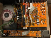


Look mum, no heatsink!
You need a service manual or schematic to have people here investigating what is wrong. Could be a free design error.
- It seems a limiting resistor to the relay coil of the loudspeaker protection circuit. This is an assumption based on the picture. This is sometimes done when for instance a 24V relay is used on 34V but also µPC1237 always has a series resistor going to the relay. R88 seems a 1 kOhm so it could also be the standard output resistor of µPC1237 to the relay. That might need upgrading to a physically larger higher power rated one to divide the heat by relatively small dissipation over a larger part surface to the environment.
G5Z-2A takes 22 mA (1W) at 24V. Just wild guessing but that would mean R88 dissipating 0.5W in the most optimal case.
From what I heard these Mira are unreliable and often have bad soldering too. Someone sure had a fun time painting electrolytic caps and transistors in colors for a colorful sound 😉
https://www.unisonic.com.tw/uploadfiles/836/part_no_pdf/UPC1237.pdf
Last edited:
I think I solved your riddle already. Please measure voltage over R88 and calculate dissipation (P = U x I -> (U x U)/R). Say thanks mentally to dr. Georg Simon Ohm: https://nationalmaglab.org/magnet-academy/history-of-electricity-magnetism/pioneers/georg-ohm/
Upgrade to a 1 or 2W resistor that fits physically so with same length but thicker body and also make sure you mount it not against the PCB but with 3 or 4 mm space between PCB and resistor for sufficient air flow. When there are no PCB tracks at the bottom/middle side I sometimes drill a 4 or 5 mm hole for more air flow and deburr the hole with an old 8 mm drill.
Upgrade to a 1 or 2W resistor that fits physically so with same length but thicker body and also make sure you mount it not against the PCB but with 3 or 4 mm space between PCB and resistor for sufficient air flow. When there are no PCB tracks at the bottom/middle side I sometimes drill a 4 or 5 mm hole for more air flow and deburr the hole with an old 8 mm drill.
Last edited:
Thanks Jean-Paul for your analyse!
Here is the schematics that I found on the internet.
According to the schematics, the protection IC is "TA7317P" (U3) and the 1K resistor is "R61".
It is a particular "1K0/MFR5" resistor.
Google said "Metal film resistors typically have a higher power handling capability compared to carbon resistors. This means that they can dissipate more heat without degrading their performance, making them suitable for applications where high power levels are involved. Carbon resistors may overheat and fail when exposed to high power levels for extended periods."
When I will find the motivation, I will try to measure the resistor voltage and calculate the dissipation at the resistor.
Then, the resistor replacement could be considered.
Thank you again,
Johan
Attachments
All I had was a picture but TA7317 is similar in function to µPC1237. Focus is the R88 1 kOhm resistor. I hope you will find the motivation, time and energy to measure the voltage and do the calculation to consider replacement of the hot resistor.
The part numbers in the revision/version of your Rega are very not similar to those in the schematics 😉
The part numbers in the revision/version of your Rega are very not similar to those in the schematics 😉
Last edited:
Hello Jean-Paul, all,
I had to reopen my MIRA to rework some dry soldering.
By the way, I measured the voltage drop at the 1k resistor: 19V.
With the formula, the dissipated power is about 0.36W, not so much I guess for a MFR5 resistor ?
I had to reopen my MIRA to rework some dry soldering.
By the way, I measured the voltage drop at the 1k resistor: 19V.
With the formula, the dissipated power is about 0.36W, not so much I guess for a MFR5 resistor ?
No as your self made FLIR pictures tell 0.36W is a lot to dissipate for such a small resistor. So much that the resistor becomes 84.1 degrees which most would call "very hot, requiring action". The diagnose and all the info to solve it in 15 minutes has already been given 4 months ago. If 19V needs to be dropped that is plain bad design, a higher voltage rated relay would be a better choice. If that Omron G5Z-2A relay is for instance 24V rated a 24 + 19 = 43V so a 36V rated one with smaller value series resistor or maybe even a 48V relay with 0 Ohm jumper possibly are a better choice. Way less heat. Choose a relay with 8A rated silver contacts with same pinout. The Omron is wimpy with only 5A rated contacts and therefore another failure possibility.
BTW rework all solder joints for reliability purposes.
BTW rework all solder joints for reliability purposes.
Last edited:
- Home
- Amplifiers
- Solid State
- REGA MIRA 2000 – Internal thermal behaviour (resistor is coming hot)