I’ve been running an Aikido 24V preamp (6GM8) but only recently came around to trying to fix an annoying channel imbalance.
Output on the scope is as per photo. I’ve changed tubes around with no meaningful effect (switching channels) but the issue doesn’t seem tube related.
B+ is 24.2V, coming from a Salas regulator (probably overkill here). I see voltages across the circuit being 0.2V lower one one channel. Checked the caps (fine), measured resistors in situ (fine), reheated solder joints, disconnected the headphone driver circuit (R19). All to no avail…
Any ideas?
Check the voltages across the heaters. With four in a series string (6GM8 tubes were not intended for series use) some might be running "hot" and some "cool".
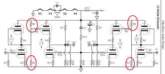
As the Aikido is direct coupled, any imbalance between the triodes of the input tube can affect the balance of the triodes of the output tube and vise versa. This can possibly be mitigated by changing the "stack" resistors between the input tube and the output tube. R5 and R6 in the attached schematic. These might be different numbers on your board. These resistors are typically 1 Meg. Try changing these out to 100K. It will make a miniscule difference in current draw, but might impose some balance on dissimilar triodes. With a B+ of 24 volts you could even try ~25K resistors.
Compare voltages across R2 and R4 (should be the same) or whatever the designation is on your board. Also R8 and R11.
I've built a couple of LVs, minus headphone circuit, and didn't notice any imbalance, but now I'm curious....
Steve
Attachments
First connect both scope probes to the same output, and verify the scope traces are identical.
If so, then the test equipment is ok to use. If not, check the scope settings and probes.
Connect a probe to each output of the voltage gain stage (with AC coupling).
If there is an imbalance, swap the probes. If the imbalance switches on the scope,
there is a real imbalance between the Aikido channels.
If there is not an imbalance, then check the follower stage. Perhaps one of the capacitors is bad.
I checked one of my LVs. 0.25 volts in @1,000Hz. volume pot at max. One channel had 1.74 volts out, the other 1.85 volts out. Not perfect but not too bad for tubes.
Does your volume pot not track well? Disconnect and put 100K 1% resistors across the input and see what the channels measure.
Does your volume pot not track well? Disconnect and put 100K 1% resistors across the input and see what the channels measure.
@rayma i went back to basics with everything suggested.
Indeed I had not measured the heaters. Over the 4 tubes I measured 6.31v, 6.17v, 6.23v, 6.24v. So quite good but swapping the highest and lowest heater voltage showed a slight improvement in balance.
Then I went back to the volume control, which is a lightspeed attenuator. This was well balanced, however accidentally turning the post led to imbalance again. So this is where the problem sits: when the lightspeed att is in balance, the aikido output is balance as well.
In other words I need to investigate tracking problems in the LA (either the alps pot or ldr mismatch)…
Ok, that is not surprising. If the Alps pot is linear, the problem is probably in the LDRs.

Your filament voltage tracking is very good. Better than most in a string of four.
I misspoke earlier when I wrote: "Compare voltages across R2 and R4 (should be the same) or whatever the designation is on your board. Also R8 and R11."
Voltages across the "upper" and "lower" cathode resistors of each particular tube will always be the same because they are in series. I you want to see how well the triodes in any particular tube match measure the plate to cathode voltages. With 15% to 20% can be considered a fairly good match.
I put a new (NOS Telefunken) set of tubes in my LV. With volume at max and 0.25v in, 1,000Hz, the output voltage was 1.41 L, 1.35 R. The odd thing when measuring DC voltage across R2 (input tube lower resistor) it was 0.85 left and 0.83 right (220 ohm resistors). Across R11 (output tube lower resistor) it was 0.71 left and 0.54 right (across 160 ohm resistors). Moving these four tubes around to various positions I got better output tube matching at the cost of slightly less good input tube matching. The output at 1,000 Hz went from a delta of 0.06 volts to a 0.09 volts. Virtually the same but there is no tube with strange low or high current draw.
I suppose the lesson here is even when you get your imbalance issues sorted out, a little bit of tube shuffling and measuring might bring your Aikido into better overall balance.
Cheers, S,
- Home
- Amplifiers
- Tubes / Valves
- Aikido LV channel imbalance