Hy,
I have a need to design a preamplifier with no gain increase, fixed eq curve, followed by 2 tone control & volume control.
I had build preamplifiers before, but by schematic or designed by other members; This time I would like to actually learn how to design a preamplifier.
I know that I need to know input & output impedance, how much gain is needed, balanced / unbalanced, single/dual rail, what other functions are needed...
I would use LS Spice for simulations.
My plan is to find an eq curve via computer (line in - line out) and replicate it as much as I can.
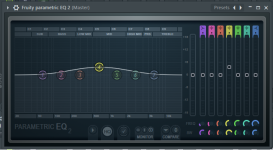
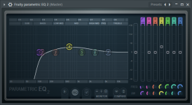
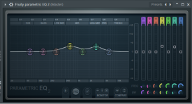
By ear, I need mid tones boost, curve will probably look something like this:
I would like to use NE5532 / TL072.
I still need to do a research on how to find / measure the impedance, but I will have 2 input sources, mono, power supply is not determined yet at this stage.
Now I will try to arrange the stages, please correct me as there will surely be an error.
1.) BUFFER (to avoid input impedance differences) -> 2.) calculated PASIVE BANDPASS FILTER (to lift the mid tones) -> 3.) GAIN STAGE (to get back to the gain, that passive filter took) -> 4.) ACTIVE TONE CONTROL (is this passive filter followed by gain stage? ) -> 5.) VOLUME POT (rather at the end than at the start of the chain, so it can also attenuate any hiss / buzz).
Does this sound correct? Should 3.) GAIN STAGE be moved just before the 5.) VOLUME POT, so 4.) ACTIVE TONE CONTROL can work with lower gain, reducing need of higher voltage from power supply? In this case would I need another buffer to avoid interference between 2. calculated BANDPASS FILTER & tone control?
Also if I would need mid boost and LFP for example, can this be done in one stage or do I need to make two stages? also for example if I would need boost at for example 500Hz and also at 2kHz, can this be done in single stage or do I need two? (Concern of 2 passive filters interfearing each other... again)
I know that I need to use coupling capacitors on inputs / outputs, to filter out DC, as far as I understand only concern in choice of such capacitor is cutoff frequency, so capacitor don`t filter out anything audible.... is there anything else?
Probably input / output impedance must be taken into account, to calculate capacitor value, but around 1uF would be the ballpark value?
This would be it for now, I still need to do some research about various factors, later I would come back with more questions as needed.
Thank you for your time 🙂
I have a need to design a preamplifier with no gain increase, fixed eq curve, followed by 2 tone control & volume control.
I had build preamplifiers before, but by schematic or designed by other members; This time I would like to actually learn how to design a preamplifier.
I know that I need to know input & output impedance, how much gain is needed, balanced / unbalanced, single/dual rail, what other functions are needed...
I would use LS Spice for simulations.
My plan is to find an eq curve via computer (line in - line out) and replicate it as much as I can.
By ear, I need mid tones boost, curve will probably look something like this:

I would like to use NE5532 / TL072.
I still need to do a research on how to find / measure the impedance, but I will have 2 input sources, mono, power supply is not determined yet at this stage.
Now I will try to arrange the stages, please correct me as there will surely be an error.
1.) BUFFER (to avoid input impedance differences) -> 2.) calculated PASIVE BANDPASS FILTER (to lift the mid tones) -> 3.) GAIN STAGE (to get back to the gain, that passive filter took) -> 4.) ACTIVE TONE CONTROL (is this passive filter followed by gain stage? ) -> 5.) VOLUME POT (rather at the end than at the start of the chain, so it can also attenuate any hiss / buzz).
Does this sound correct? Should 3.) GAIN STAGE be moved just before the 5.) VOLUME POT, so 4.) ACTIVE TONE CONTROL can work with lower gain, reducing need of higher voltage from power supply? In this case would I need another buffer to avoid interference between 2. calculated BANDPASS FILTER & tone control?
Also if I would need mid boost and LFP for example, can this be done in one stage or do I need to make two stages? also for example if I would need boost at for example 500Hz and also at 2kHz, can this be done in single stage or do I need two? (Concern of 2 passive filters interfearing each other... again)


I know that I need to use coupling capacitors on inputs / outputs, to filter out DC, as far as I understand only concern in choice of such capacitor is cutoff frequency, so capacitor don`t filter out anything audible.... is there anything else?
Probably input / output impedance must be taken into account, to calculate capacitor value, but around 1uF would be the ballpark value?
This would be it for now, I still need to do some research about various factors, later I would come back with more questions as needed.
Thank you for your time 🙂
Last edited:
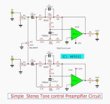
Pretty standard active tone circuit. But the impedance level is too high. Normally you would use 10k or 20k pots.
To start, I would divide all resistors by a factor of five (or ten), and increase all capacitors by a factor of five (or ten).
Also, use the 5534 instead, which will allow identical PCB layouts for each channel.
To start, I would divide all resistors by a factor of five (or ten), and increase all capacitors by a factor of five (or ten).
Also, use the 5534 instead, which will allow identical PCB layouts for each channel.
Ok.
I don't see point in using this schematic, if I need to modify that much right away, but anyway I appreciate it for learing purpose.
Will search a bit more to find something similiar with values in mind.
Also I will make mine in mono -that's what the project calls for.
I don't see point in using this schematic, if I need to modify that much right away, but anyway I appreciate it for learing purpose.
Will search a bit more to find something similiar with values in mind.
Also I will make mine in mono -that's what the project calls for.
The book Small Signal Audio Design by Douglas Self is plenty of examples plus the necessary data to calculate them.
Have a look at rod elliott's designs, with tone controls:
https://sound-au.com/project97.htm
Without tone controls, but still worth reading:
https://sound-au.com/project88.htm
https://sound-au.com/project97.htm
Without tone controls, but still worth reading:
https://sound-au.com/project88.htm
Wholeheartedly agree.The book Small Signal Audio Design by Douglas Self is plenty of examples plus the necessary data to calculate them
Also Bob Cordell’s new book dives in early on into a preamp design and has chapters on tone controls and filters and even a whole chapter on better volume controls and balance controls.
Both are extremely useful for someone with an interest in preamp design and cost less than building a really good one!
Can you clarify your purpose for the mono preamp?
Also, what are the sources, loads, and gain needed?
Also, what are the sources, loads, and gain needed?
Thank you all for your inputs.
I will do some reading and return.
Let me do a quick writeup on where I`m going with this:
I`m modifying 70s Yugoslavian radio, Iskra Savica SN120:
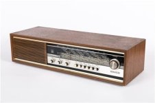
This radio has specific sound, only 3w 4ohm (12cm x 17.5cm) speaker. Sound is warm, soft, strong mid tones, it somehow manages to fill the whole house.
A great achievement for the time being, many many households had it. And I want to replicate the sound as much as I can with new amplifier.
Everything is gutted out, only speaker remains. I had managed to build tuner with MCU and Sony TUX-032 tuner module from Xplod car radio. Scale pointer is morised with a stepper motor.
That results in auto tune tuner with great reception.
My plan was to do the project in STEREO, but radio was originaly in MONO and setting tuner to MONO mode results in so much cleaner sound, I decided to keep it in MONO.
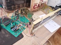
I still need to do a research on how to find INPUT IMPEDANCE. The tuner (Sony TUX-032) has no datasheet, so it would need to be measured, other source will be bluetooth module (I didn`t choose one yet).
OUTPUT IMPEDANCE... I didn`t choose the amplifier yet, but most likely it will be transistorised amplifier.
I will do some reading and return.
Let me do a quick writeup on where I`m going with this:
I`m modifying 70s Yugoslavian radio, Iskra Savica SN120:

This radio has specific sound, only 3w 4ohm (12cm x 17.5cm) speaker. Sound is warm, soft, strong mid tones, it somehow manages to fill the whole house.
A great achievement for the time being, many many households had it. And I want to replicate the sound as much as I can with new amplifier.
Everything is gutted out, only speaker remains. I had managed to build tuner with MCU and Sony TUX-032 tuner module from Xplod car radio. Scale pointer is morised with a stepper motor.
That results in auto tune tuner with great reception.
My plan was to do the project in STEREO, but radio was originaly in MONO and setting tuner to MONO mode results in so much cleaner sound, I decided to keep it in MONO.

I still need to do a research on how to find INPUT IMPEDANCE. The tuner (Sony TUX-032) has no datasheet, so it would need to be measured, other source will be bluetooth module (I didn`t choose one yet).
OUTPUT IMPEDANCE... I didn`t choose the amplifier yet, but most likely it will be transistorised amplifier.
Good 🙂 For now I will try to build this & the amplifier and do some listening to decide if I really need that "fixed eq curve part". It might very well be that speaker & wooden cabinet partly open at the back gives alot of sound characteristics and a bit of bass boost from the tone control might to the trick. In that case I can add resistor to the pot, to alter the minimum boost. Also the tuner has rather "boomy" sound -typical for late 90s hifi.
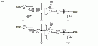
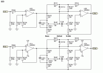
Thats the output stage of the same project, do I need it? And why is it needed? Impedance matching or something else? Would the input impedance of the amp alter the filter properties if no output stage is used? Can I just put volume pot after the tone control and forget the output stage?
EDIT: I`m sorry, ofcourse, it`s for phase correction.
- Home
- Design & Build
- Electronic Design
- I want to learn preamplifier design
