I'm not sure if anyone is familiar with Gavitt shielded wire. I'm old enough to remember seeing it in audio equipment, both professional and consumer. It is a braided shielded type with no outer covering, the braided shielding is exposed. The inner conductor has cloth insulation and is tinned. I'm doing an amplifier build and bought a length of the wire. The combination of braided shield, cloth insulation and tinned inner conductor helps the wire hold its shape. The absence of insulation over the braided shield probably also helps. The cons of using this type of shielded wire is the extra time and work involved. I usually only connect shields at one end of a shielded wire. However, the braided shield needs to be unbraided at both ends. I used a sewing needle to pull the braid loose. This is time consuming and one has to be careful not to damage the inner conductor cloth insulation. I used shrink tubing at the end of the braid, also over the end of the cloth insulation to prevent the insulation from fraying.
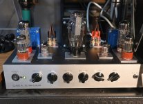
The amplifier is a two channel (stereo) Class A ultra-linear using a single output tube. Output tubes are 6L6GC or KT66. I will also try 6CA7s. The power transformer has sufficient rating to handle the extra filament current. The rectifier is a 5U4. There are three stereo inputs, each input has its own level control. Over the years, I have found input selector switches to be troublesome with dirty or worn out contacts. The other controls are balance plus low and high adjust tone controls. My listening area is small, I don't need a lot of power. I have also found that, to me, Class A operation produces a more pleasing sound than push-pull.

The amplifier is a two channel (stereo) Class A ultra-linear using a single output tube. Output tubes are 6L6GC or KT66. I will also try 6CA7s. The power transformer has sufficient rating to handle the extra filament current. The rectifier is a 5U4. There are three stereo inputs, each input has its own level control. Over the years, I have found input selector switches to be troublesome with dirty or worn out contacts. The other controls are balance plus low and high adjust tone controls. My listening area is small, I don't need a lot of power. I have also found that, to me, Class A operation produces a more pleasing sound than push-pull.

Class A can be SE or PP. SE must be class A but PP can be A, B or AB.I have also found that, to me, Class A operation produces a more pleasing sound than push-pull.
If you run output tubes Class A in a PP configuration, you are still splitting the signal, then combining it back together at the output. A PP configuration operated Class A is going to require a reduction of power output to keep the output tubes below maximum plate dissipation. You could run two output tubes in parallel Class A, eliminate the phase inversion process, and get about the same power output. Less parts, less signal manipulation. Less is always better🙂
Wasn’t referring to topology, only that your statement implies that only SE is class A. PP can be class A too.
Looks similar underneath to vintage equipment from the 50s and before.
I have seen some tubular braid for sale on a local auction site, and was thinking that could be an interesting way to protect sensitive wiring.
I have seen some tubular braid for sale on a local auction site, and was thinking that could be an interesting way to protect sensitive wiring.
I sometimes use something similar, a roll of shielding braid.
A friend's father worked in radar and gave me his entire stock.
You can still find some but it's very expensive.
https://hebotec.de/fr/produits/detail-du-produit/tresse-de-blindage-2050-001a
A friend's father worked in radar and gave me his entire stock.
You can still find some but it's very expensive.
https://hebotec.de/fr/produits/detail-du-produit/tresse-de-blindage-2050-001a
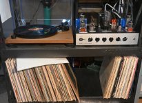
Antique Electronic Supply is where I purchased the Gavitt wire. The amplifier is pretty much done. I am using it for awhile before I do a couple finishing things. I ran into a problem where the 12AX7s were picking up data interference. I could eliminate most of the interference by placing a shield over the 12AX7s. But, tube shields ruin the clean look of the amplifier. I mounted the filter choke and large filtering caps inside the chassis mainly to keep the top side of the chassis clean. It also allowed using a smaller size chassis. The interference source turned out to be my T-Mobile internet box. The jack on the amplifier front panel is for headphones. I did not own any headphones, so I ordered an Audio-Technica ATH-M50X headphones. I need the headphones to make sure my output pad values are correct. The speaker binding post are spaced to accept a double banana plug. For headphone use, the speakers are unplugged. The amplifier can be run without an eight ohm load. For headphones, the headphone pad provides the load. At some point, I'll take some test readings.
Attachments
- Home
- Amplifiers
- Tubes / Valves
- Gavitt Shielded Wire