Good afternoon all,
I have recently noticed the PCB in my ARC preamp has quite a bit of discoloration around a stack of 6 resistors near the 6550 tube. A quick Google search revealed ARC must have reworked that part and used a single high power resistor later on.
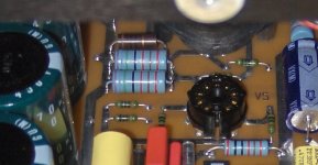
Does anyone know the value of the parts there? The resistors look like 6x 1.5k in parallel giving 250 ohm but what about the carbon resistor next to them? I've tried to find pictures of other REF5's but none are clear enough to read the value of the carbon one and the single power resistor they used later.
I have recently noticed the PCB in my ARC preamp has quite a bit of discoloration around a stack of 6 resistors near the 6550 tube. A quick Google search revealed ARC must have reworked that part and used a single high power resistor later on.
Does anyone know the value of the parts there? The resistors look like 6x 1.5k in parallel giving 250 ohm but what about the carbon resistor next to them? I've tried to find pictures of other REF5's but none are clear enough to read the value of the carbon one and the single power resistor they used later.
Last edited:
Isn't the carbon resistor connected to the grid? That is ok to use there.
Just measure the six paralleled resistors, they should still be nominal.
The solder joints look bad.
Just measure the six paralleled resistors, they should still be nominal.
The solder joints look bad.
It looks like a lot of burnt crusty flux left on the board. So 96% isopropyl alcohol will normally clean that off, with a cotton swab..
You could also just de- solder one of the six, and measure.
You could also just de- solder one of the six, and measure.
The schematic isn't available, I removed the 6 stacked resistors and all measured fine at 6x 150kOhm giving 25kOhm total. They will all be replaced by 1 or 2 high power resistors and mounted away from the PCB.
ARC's decision to stack them was rather questionable, the lower row was touching the PCB which caused such discoloration.
ARC has replaced it with a single 27k looks like:

ARC's decision to stack them was rather questionable, the lower row was touching the PCB which caused such discoloration.
ARC has replaced it with a single 27k looks like:
Last edited:
Does someone know the brand of the light blue resistors ARC uses? Can't seem to find these anywhere.
Also, is it possible to make an estimate of the maximum heat dissipation of a resistor knowing the body is 11x3mm?
Also, is it possible to make an estimate of the maximum heat dissipation of a resistor knowing the body is 11x3mm?
Absolutely agree, however it's almost impossible to find 20kOhms 1% tolerance (need 2 times 20kOhms) and 2W+ dissipation which makes me think I'm must be looking for too high power dissipation than the current ones.
Calculate the actual power dissipation by V x V / R and at least double that for the rated dissipation needed,
preferably more. Which 6550 tube pin does the resistor connect to? Probably the screen like the Ref 2.
Maybe someone here has a schematic.
preferably more. Which 6550 tube pin does the resistor connect to? Probably the screen like the Ref 2.
Maybe someone here has a schematic.
Drew a circuit of the Ref3 regulator once, 15-20 years ago. Probably 95% accurate. It should be a matter of 10 min to update it for the Ref5.
Amazing how many reference and anniversary regurgitations of the same simple topology are out there. With the same $2 chip in the volume control. And every next one much better sounding 🙄
Amazing how many reference and anniversary regurgitations of the same simple topology are out there. With the same $2 chip in the volume control. And every next one much better sounding 🙄
Attachments
Thank you, I seem to be missing the 2 big blue 75k and single 20k resistor on your schematic? Just curious.
Interesting to see the 5 has a heftier resistor there and roughly the same circuit is still in use in the REF6SE even.
Interesting to see the 5 has a heftier resistor there and roughly the same circuit is still in use in the REF6SE even.
This is a rather weird design, the voltage drop over these resistors is 440V (!). Makes one think if there was no neater way to do this. With solutions like this it's no surprise it draws 120W from the mains socket, ha.
Even after replacing them with quadruple R's for a total of 20W they ran at 170 degrees. Changing the PSU tubes for fresh ones lowered the temperature further to 100 degrees celsius but I'm still unhappy with such a crude design.
Even after replacing them with quadruple R's for a total of 20W they ran at 170 degrees. Changing the PSU tubes for fresh ones lowered the temperature further to 100 degrees celsius but I'm still unhappy with such a crude design.
- Home
- Amplifiers
- Tubes / Valves
- ARC Ref5 PSU resistors question