Hi all,
Hopefully there are some op-amp experts here. I am making a mic. preamp board and will be using the PGA2505 IC for amplifying the input signal.
However, I am trying to decide on an op-amp for various audio roles: audio peak-detect circuit, low-pass filtering, buffering, and a balanced line driver. I could use different op-amps but prefer to consolidate to one.
I have +-5V rails available so will be using dual-supply and obviously rail-to-rail input and output is a necessity.
Initially I was going to use the NE5532 but saw the TI recommends the TLV9362 as a replacement.
Searching TI audio op-amp sections revealed the LME49721.
Then there are more general purpose options: AD8542 and TLV9002
Here are some stats.
| TLV9002 | AD8542 | TLV9362 | LME49721 | |
|---|---|---|---|---|
| Cost $ (USD) | $0.4 | $0.87 | $1.0 | $1.1 |
| Noise (nV√Hz) at 1kHz | 30 | 40 | 8.5 | 4 |
| Offset voltage (mV) | 1.5 | 6 | 1.7 | 1.5 |
| Slew rate (V/µs) | 2 | 0.75 | 25 | 8.5 |
- I like the TLV9002 for the cost but is 30 nV√Hz acceptable for audio?
- Maybe for peak-detect this would be OK, but probably not for anything in the signal path?
- Is there a compelling reason to pick the TLV9362 over the LME49721 (other than cost)?
LME49721 will go up in smoke at your supply voltage. It is meant for at most 5.5 V between the positive and the negative supply, while you have 10 V. The same applies to the TLV9002 and AD8542.
Hi MarcelvdG,
Did I miss something? Yes! These seem for total voltage 5V, was reading the info. Wrong!It seems alright to me, for +-5V rails, from the webpage (both TVL9002 and LME4972 say the same)

What about the AD8542? This seems to imply it’s OK?

Regards,
Dan
Did I miss something? Yes! These seem for total voltage 5V, was reading the info. Wrong!
What about the AD8542? This seems to imply it’s OK?
Regards,
Dan
Last edited:
No, the underlined part doesn't mean it can be powered with +/-6V just that being a differential input it can go to 6V magnitude both ways without either of the inputs going negative.
As for your 30nV/rtHz question - it depends how high fidelity you're looking for and the particular circuit configuration. The input noise would be around 4uV in the audio band or -107dBV.
As for your 30nV/rtHz question - it depends how high fidelity you're looking for and the particular circuit configuration. The input noise would be around 4uV in the audio band or -107dBV.
Hi Dan,
Like abraxalito, I'm afraid it doesn't mean it is OK.
Suppose you connect the positive supply pin to +5 V and the negative supply pin to 0 V. The voltage between the positive and negative supply pins is then 5 V, obviously.
Now connect the positive input to the positive supply pin and the negative input to the negative supply pin. The differential input voltage will then be +5 V - 0 V = +5 V.
When you swap the inputs, the differential input voltage becomes 0 V - (+5 V) = -5 V.
Best regards,
Marcel
The one remaining op-amp has a rail-to-rail output, but no rail-to-rail input.
One thing you should know about rail-to-rail inputs: there are exceptions, but the traditional way to make them is by giving the amplifier two input stages, an N-type (for example, NMOS or NPN) stage for medium and high common-mode input voltages and a P-type (PMOS or PNP) input stage for medium and low common-mode input voltages. These stages normally have different offset voltages, as they have independent random mismatch. When you make a voltage follower and drive it through the voltage range where the op-amp transitions from one input stage to both or from one to the other, the offset changes with the signal, causing extra distortion.
One thing you should know about rail-to-rail inputs: there are exceptions, but the traditional way to make them is by giving the amplifier two input stages, an N-type (for example, NMOS or NPN) stage for medium and high common-mode input voltages and a P-type (PMOS or PNP) input stage for medium and low common-mode input voltages. These stages normally have different offset voltages, as they have independent random mismatch. When you make a voltage follower and drive it through the voltage range where the op-amp transitions from one input stage to both or from one to the other, the offset changes with the signal, causing extra distortion.

Not rail-to-rail though. Well specifically not rail-to-rail on the inputs, as there is 3.5V drop-out - the outputs have good swing, so as a gain stage it's fine, but as a follower it would be hopeless at +/-5V as the input only works to +1.5V...
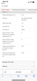
For theTLV9362 what is the input signal headroom swing? I could scale the input signals down.
Am I reading this right: the output signal can swing to 0.06V of the rails; at the input it can swing to the negative rail but only Vs-2V of the positive rail?
Am I reading this right: the output signal can swing to 0.06V of the rails; at the input it can swing to the negative rail but only Vs-2V of the positive rail?
Attachments
Yes, but note that output swing is always load-depedent, often there's graphs to show the dependence of output swing on output load or current.
Found it! It is down 1V at 40mA (room temperature). Thanks.often there's graphs to show the dependence of output swing on output load or current.
- Home
- Design & Build
- Parts
- Advice on low-cost op-amps for audio applications: LME49721 vs TLV9002 vs AD8542 vs TLV9362