I have two of these that appear to have the same symptoms.
When I got both, the power supply side was blown, and nothing appeared to be wrong on the output section.
They had H1 marked MOSFETS with 4.7-ohm gate resistors. The driver IC was marked C12.
I installed new IRF1404 and new 4.7-ohm gate resistors. I replaced the C12 with MIC4427 in both.
They both behave the same way, but let's focus on one, we'll call amp A.
I have Amp A powering up through 2-ohm limiting resistance. It does produce clean audio output at the speaker terminals.
With my power supply set at ~13.9V to get 10V at the B+ and GND terminals it is drawing ~5.2A at idle.
I measure 65.22V between - Speaker terminal and GND, 65.41V between + Speaker terminal and ground.
I measure 9.97V at the positive pin on the TL072 and the TL074 ICs
On the 15V regulator, at startup I measure ~24.2V on the input and ~15.23V on its output. Once the amp is stabilized and on, the input drops to ~14.8V and 13.29V on the output.
On the 5V regulator, at startup I measure ~12.5V on the input and 5V on its output. Once the amp is stabilized and on, the input drops to ~9.16V and 5V on the output.
If I leave the amp on for several minutes, only the power supply side of the heatsink gets warm.
I have now altered amp A from the other one in that I changed the power supply gate resistors from 4.7-ohm to 10-ohm and I changed out the 15V regulator also. That made no change.
Is the problem something powered by that 15V supply?
Attachments
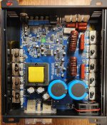
What happens if you don't limit current (all FETs clamped to heatsink)? Limit with a 15 amp fuse if you're concerned about damage.
I dialed back my power supply to 11V and it sagged to ~10.5 while drawing ~6A no audio input.
The 15V regulator shows ~15.5V on the input and ~14.5V on the output while on.
The 15V regulator shows ~15.5V on the input and ~14.5V on the output while on.
Is the supply regulated? If you provide 13v, does the pulse width decrease, along with the current draw?
Pulse width does not change. I do not know if it should, I suspect it should this series of amplifiers is supposed to provide the same output power level at 2 or 1 ohm loads.
As I adjust the voltage up from 11V with the amp on, the current draw increases but once I get to 12V the current draw does descend some. It also becomes not a steady draw; it bounces as high as 7A down to 4A. Once I get to 13V, it bounces from as high as 6A down to 4A. Increasing to 14V doesn't really show much difference to 13V.
While watching for pulse width to change, what is changing is the amplitude in sync with the current draw pulses.
Does the rail voltage continue to increase as you increase the B+ voltage?
Where are you checking the pulse width?
Where are you checking the pulse width?
I haven't checked the rails since powering it unrestricted. I measure steady ~71V on each speaker terminal from 11V up to 14.5V.
Checking for pulse width on one of the gates of the power supply MOSFETs.
Checking for pulse width on one of the gates of the power supply MOSFETs.
Taking measurement between GND and one of the outer legs of the rectifier, I measure ~50V there when 11V is on B+ that climbs to ~65.5V when 14V is on B+.
Max steady idle current draw happens around 11.7V - 12.5V area on B+ which is about 7.3A
Max steady idle current draw happens around 11.7V - 12.5V area on B+ which is about 7.3A
The outer legs have a square wave unless the amp uses doublers (not likely). The center leg would be DC and likely about 135v.
If the rail voltage varies in proportion to the B+ voltage, there is no regulation.
Are you sure that you have 4.7 ohm gate resistors installed? Measure them to confirm.
If the rail voltage varies in proportion to the B+ voltage, there is no regulation.
Are you sure that you have 4.7 ohm gate resistors installed? Measure them to confirm.
I'll remeasure
This amp has 10 Ohm gate resistor installed. Originally had 4.7 and didn't behave differently.
This amp has 10 Ohm gate resistor installed. Originally had 4.7 and didn't behave differently.
What behavior are you referring to? I'm interested in the high idle current and heating of the PS FETs. Are you saying that the FETs ran hot and the amp drew precisely the same current with the 4.7 ohm resistors?
I'd say the outputs of both driver Ic's look really good. Both driver IC's look the same, high side to high side and low side to low side.
If anything, the low side of both IC's is slightly rounded left side top corner of waveform.
This amp is using 1 ohm gate resistors between the IC and outputs.
If anything, the low side of both IC's is slightly rounded left side top corner of waveform.
This amp is using 1 ohm gate resistors between the IC and outputs.
Ah, sorry my misunderstanding.
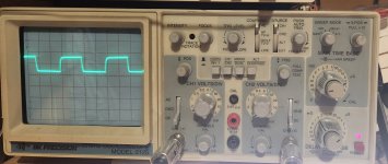
Picture attached taken at ~11.5V on B+ because it is a stable waveform. Probe set to x10. Scope set at 2V per division, time base at 5uS and the trace is aligned to the center. All gate legs look the same.
Now when I increase that voltage at B+, the quality of square waveform is the same but as I stated earlier when the amp starts fluctuating its current draw, the bottom of the waveform remains stable and in place, but the top of the waveform fluctuates up and down a few divisions.
Attachments
- Home
- General Interest
- Car Audio
- Sundown SIA-2500D