So as a retired mechanical engineer I take interest in how the layout and assembly features are handled by different manufacturers. So, I have a Krell 300-s amplifier apart and was really intrigued by how they chose to attach boards and casings. This is my amp and it's the first time I've had it apart. It was in climated controlled storage for about 4-5 years. Set it up and turned it on and no right channel. Reviewing the power supply board and found (2) 5ohm 5watt resistors that were open. Replaced those and was able to start it until it went into action and failed. Removed the output board and the driver board. Found some parts that were cooked from the start up. Fix those and the next time, no right channel.
Starting with the power supply board I found the same 5 ohm 5 watt resistors opened again.
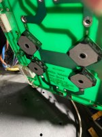
This lead me to disassemble the power supply board with the 68,000 ohm 100v capacitors on it. Two things struck me as really odd. First, the board is not attached to the case. It is in free suspension with only the straps coming from driver board suspending it. Certainly not the way I would do it since it would be susceptible to stress when moving the amp. But the real problem was how the large capacitors were attached. They were attached by only one screw and the other post was allowed to make contact only from the friction of the other screw holding to the board. I had originally thought there was a screw that went though the center of the bridge rectifier that would secure the other post, but no. This is without a doubt the most unusual and potentially dangerous way I can imagine. The first capacitor I removed (once again only one screw holding it) had been arcing off the contact land on the circuit board where there was nothing securely attaching it to the board other than the other post that did have a screw.
I would love to think that this had been worked on before I bought it and they forgot to install the screws for the other post. If someone out there has any information on this I would love to hear from you.
John
Starting with the power supply board I found the same 5 ohm 5 watt resistors opened again.
This lead me to disassemble the power supply board with the 68,000 ohm 100v capacitors on it. Two things struck me as really odd. First, the board is not attached to the case. It is in free suspension with only the straps coming from driver board suspending it. Certainly not the way I would do it since it would be susceptible to stress when moving the amp. But the real problem was how the large capacitors were attached. They were attached by only one screw and the other post was allowed to make contact only from the friction of the other screw holding to the board. I had originally thought there was a screw that went though the center of the bridge rectifier that would secure the other post, but no. This is without a doubt the most unusual and potentially dangerous way I can imagine. The first capacitor I removed (once again only one screw holding it) had been arcing off the contact land on the circuit board where there was nothing securely attaching it to the board other than the other post that did have a screw.
I would love to think that this had been worked on before I bought it and they forgot to install the screws for the other post. If someone out there has any information on this I would love to hear from you.
John

With almost everyone on the planted owning a camera, it should be your first action. A picture tell a thousand words.
The second most important thing is to tell us why you opened it in the first place, curiosity killed the cat. Then thirdly would be what you did and why. As a seasoned engineer, you never say I did nothing, it just happened. I don't think that the product would have sneaked through their quality process. If it was in storage for that length of time, it was placed there for a reason maybe it stopped working and before discarding it it went to storage because of some emotional attachment to it.
Come to think of it, the power supply is probably the most robust part of the amplifier, something on it burned due to a downstream failure. Immediately you see something floating unattached you should immediately have reacted to where the fixing hardware went to? It may have fallen into an area shorting out some critical component.
A lot of people would argue that a fuse have blown, but the fuse is upstream and those capacitors hold an enormous amount of energy which in a fault condition can discharge that energy instantaneously, long before a fuse would even warm up, let alone blowing.
Fixing electronics without any documentation can be a daunting task. Scan the internet to see if you can find the schematics of your amplifier. We will assist you as well as we can. Do you have any test equipment, or at least a digital multi-meter?
Sounds like one capacitor terminal bolt loosened and is missing.
Thermal stress and vibration will do that. A bad shipping experience?
Thermal stress and vibration will do that. A bad shipping experience?
To clarify, I’ve owned the amp for many years. It went into storage because I wasn’t using it. I have numerous amplifiers and was rotating it through my system. After setting it up the right channel was out.
Of course I have the schematic for it, but you must be aware that I’ve never seen an electronics company share a mechanical drawing which would be where the mechanical configuration would be shown.
I don’t think I mentioned needing help with troubleshooting the amp, I was just trying to get some insight on the design that they used for attaching the capacitors and see if anyone else had information on it.
I will attach pictures when I return home today.
John
"I don’t think I mentioned needing help with troubleshooting the amp, I was just trying to get some insight on the design that they used for attaching the capacitors and see if anyone else had information on it.
Well that makes it easy not having to troubleshoot the amp. Unless someone here worked at Krell in the design department, physically have one open in front of him or more specifically worked on KSA300, may he/she step forward. This amp was first reviewed around 2010 and 14 roughly years old, this is young for such an animal.
You said you were a mechanical engineer. You should be able to tell by inspection how they used to attach capacitors unless the hardware was removed and binned.
Last edited:
"You said you were a mechanical engineer. You should be able to tell by inspection how they used to attach capacitors unless the hardware was removed and binned."
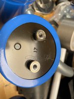
Yes and this is where it gets interesting. It was designed to accomadate a screw going the rectifier and through the circuit board and fastening to the lug of the capacitor. There were only 4 screws attaching the 4 capacitors to the board.
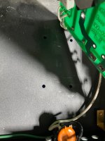
I took some pics that shows some clues. It appears there had been screws originally that came up through the bottom of the case. You can see the arcing on the board and the top of the post on the capacitor.
John

Yes and this is where it gets interesting. It was designed to accomadate a screw going the rectifier and through the circuit board and fastening to the lug of the capacitor. There were only 4 screws attaching the 4 capacitors to the board.
I took some pics that shows some clues. It appears there had been screws originally that came up through the bottom of the case. You can see the arcing on the board and the top of the post on the capacitor.
John
Attachments

Terrible. This amplifier was abused either in shipping or repair.
Of course large, heavy parts are intended to be mechanically secured.
Of course large, heavy parts are intended to be mechanically secured.
Might four screws go through the board and lining up with four of the inside terminals of the capacitors, like bridging them creating the zero volt reference
Just a wild guess, I never seen a Krell amplifier.
Just a wild guess, I never seen a Krell amplifier.
To me this is a typical case of a repair gone wrong.
Either the technician couldn't fix it, or the customer thought the quote was too high.
He quickly reassembled the device and returned it to the customer.
Either the technician couldn't fix it, or the customer thought the quote was too high.
He quickly reassembled the device and returned it to the customer.
I think I am correct, if you look at the surface of the capacitor screw terminal, one is damaged indicating something under a screw was taken of and replaced several times while the other is clean like screwing it onto a flat surface like the power supply PCB perhaps. Anyway, I am not a mechanical chap just observing what I can..
"Might four screws go through the board and lining up with four of the inside terminals of the capacitors" I believe that would be correct although 2 would be connecting to the positive post. This would cause a short if not properly isolated. The four holes I show in the chassis line up with the center holes in the rectifiers. Under the chassis you can see there was some form of attachment.
I would appreciate someone with a 300s, 200s, or a 100s to take a picture underneath the chassis to see what the screws look like.
John
I would appreciate someone with a 300s, 200s, or a 100s to take a picture underneath the chassis to see what the screws look like.
John
No there will be no shorts, if you look at the bottom of the PC board, you will see it shorting the two pairs of capacitors to positives to negatives, this shorting point represents the common or 0VDC return, it is a split rail power supply having a pos, gnd and neg. You want be to make a sketch or you understand what I am saying.

Last edited:
"No there will be no shorts" Yep I got it. I also found a picture of the bottom of a 300s and there are screws holding the capacitors. Concern solved.
Thanks,
John
Thanks,
John
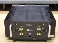
That amp (below) ??Krell 300-s
Looks like a big "Genesis stealth" Class A I worked on.
Mechanically , everything had a purpose inside. Very important that everything was properly screwed (and heatsinked).
The Genesis referenced ground from the PCB's on some modules.
I fixed the one genesis and turned the other one into a nice cool Class AB !
WOW ! that thing could heat a whole room ! Must weigh 50+ KG !!
OS
Attachments
- Home
- Amplifiers
- Solid State
- Krell KSA300S power supply