Hello everyone. I am continuing with the restoration of a Kenwood KR2010 receiver.
I have managed to correct the bias current and the DC bias of the power stage thanks to your contributions.
https://www.diyaudio.com/community/threads/kenwood-kr-2010-bias-adjustment.371991/
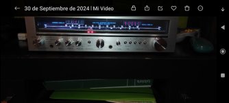
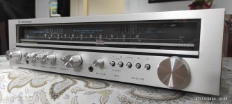
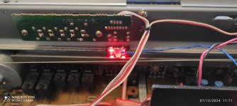
I have put LED backlighting on the tuning dial and illumination on the tuning pointer.
Now I want to reduce or eliminate the noise between FM stations, and looking in the service manual I see the IC KB4402 and I don't know how to achieve it since there is no potentiometer to adjust the mute. I appreciate your help.
I have managed to correct the bias current and the DC bias of the power stage thanks to your contributions.
https://www.diyaudio.com/community/threads/kenwood-kr-2010-bias-adjustment.371991/
I have put LED backlighting on the tuning dial and illumination on the tuning pointer.
Now I want to reduce or eliminate the noise between FM stations, and looking in the service manual I see the IC KB4402 and I don't know how to achieve it since there is no potentiometer to adjust the mute. I appreciate your help.
Attachments

Thank you very much for your contribution.Looks like it uses the AM selector as the fm mute button as well. Check the contacts there.
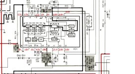
I found a diagram of KB4402.
The mute circuit has components of different values than those in the Kenwood KR2010.
Can I substitute those values? Will there be any negative consequences if I do so? La foto de KB4402 1 es elde Kenwood.
Thanks.
Attachments

Are you saying that the interstation muting is totally nonfunctional in your tuner?
And the noise is gone when tuned to a station?
And the noise is gone when tuned to a station?
Suggest you read the data sheet for the IC to find out how it is supposed to work.
The most likely fault is the muting switch being dirty, corroded, or worn out.
There may be a bad solder joints or a bad related component. Or the IC itself may be bad.
The most likely fault is the muting switch being dirty, corroded, or worn out.
There may be a bad solder joints or a bad related component. Or the IC itself may be bad.

Move the muting switch through its complete movement about ten times and recheck.
If there is any improvement, give it a good cleaning. If there is not, still clean it.
If there is any improvement, give it a good cleaning. If there is not, still clean it.
This model does not have a specific switch for mute.Move the muting switch through its complete movement about ten times and recheck.
If there is any improvement, give it a good cleaning. If there is not, still clean it.
It would seem that it would always be on or activated.
In the diagram you can see a derivation from the mute components to the AM switch that, when activated, would ground them.
I sincerely do not understand the reason for this.
On the other hand, I think that it is a 44-45 year old receiver. It could be that the cause of the mute failure is the aging of the electrolytic capacitors.
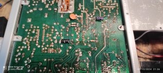
I have done the recap but of the amplifier part but I have not dared to do it on the tuner board.
In any case, I appreciate your contributions.
Problem solved.
You always have to keep looking for possible mistakes of your own.
It turns out that I had not realized that the diagram specifies that the shaded components in the KB4402 are only for the E model and the receiver I have is a model M.
In this model the places where the mute components would go are empty.
I solved it by adding them (three resistors, two electrolytic and one ceramic).
Completely muted between FM stations.
Attachments
Who can upload an image series from all internal units of KR-2010 in the similar kind than this images from KR-5400 under
https://reverb.com/item/51381461-ke...0s-solid-state-am-fm-stereo-receiver-serviced
Thank you very much.
P.S.: online there are no internal images to find - obviously, failures are rare with this model.
https://reverb.com/item/51381461-ke...0s-solid-state-am-fm-stereo-receiver-serviced
Thank you very much.
P.S.: online there are no internal images to find - obviously, failures are rare with this model.
Hi Tiefbassuebertr.
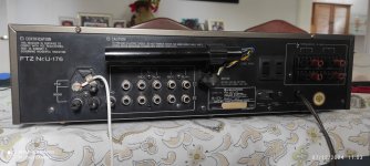
Give me time and I'll upload photos as you request.
You will find some modifications I've made such as variable resistors to adjust bias and eliminate DC on output https://www.diyaudio.com/community/threads/kenwood-kr-2010-bias-adjustment.371991/ ;
speaker switching with relay; LED illumination of the dial.
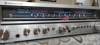
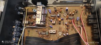
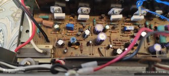
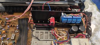
As promised.
Attachments
-
 1733581012335.jpg245.7 KB · Views: 41
 -
 1733581012572.jpg252.6 KB · Views: 42
 -
 1733581012489.jpg443.6 KB · Views: 36
 -
 1733581012442.jpg345.2 KB · Views: 37
 -
 1733581012466.jpg315.1 KB · Views: 40
 -
 1733581012424.jpg362.6 KB · Views: 37
 -
 1733581012466.jpg315.1 KB · Views: 37
 -
 1733581012370.jpg223.7 KB · Views: 37
 -
 1733581012424.jpg362.6 KB · Views: 40
 -
 1733581012553.jpg281.7 KB · Views: 39
Thank you very much for the images - I was owner of a device from exact this model between 1979 and 2009 and after refurbishing now a friend of me use it.Hi Tiefbassuebertr.
Give me time and I'll upload photos as you request.
You will find some modifications I've made such as variable resistors to adjust bias and eliminate DC on output https://www.diyaudio.com/community/threads/kenwood-kr-2010-bias-adjustment.371991/ ;
speaker switching with relay; LED illumination of the dial.
I also had replace R23+R59 by a variable resistor for adjust a idle current of around 24mA through the output power transistors (8mV over R35 and R37).
But after doing this the variable resistor I had replace again by a resistor with same value of the adjusted variable resistor (at whole 3 resistors in parallel mode).
Last edited:
- Home
- Source & Line
- Analogue Source
- Kenwood KR2010 FM noise mute