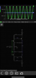
I am trying to use a simple online circuit simulator to help me understand the inner workings of the various FW designs. Figured I’d start with a simple design so starting with the F5 and specifically the simplified schematic of the F5 from Nelson’s intro to the design on page 10 here.
Something isn’t quite working right, would appreciate if anyone could help me out. I believe the schematic is editable by others.
https://everycircuit.com/circuit/6136255276122112
Something isn’t quite working right, would appreciate if anyone could help me out. I believe the schematic is editable by others.
https://everycircuit.com/circuit/6136255276122112
Attachments
Have you considered LTSpice? There’s a lot of LTSpice knowledge here. And there are already some F5 models floating around.
That said, the simplified schematics often lack the detail necessary to actually work. They are more conceptual in nature. Are the output devices in your model even conducting?
That said, the simplified schematics often lack the detail necessary to actually work. They are more conceptual in nature. Are the output devices in your model even conducting?
The R4 value is incorrect.
You might want to try the F5m schematics, which is complete and barely more complicated than the simplified circuit.
You might want to try the F5m schematics, which is complete and barely more complicated than the simplified circuit.
I have not found those models and was trying to avoid a learning curve with LTSpice. I’ll have a look but I guess I should be able to get it running on this online tool.Have you considered LTSpice? There’s a lot of LTSpice knowledge here. And there are already some F5 models floating around.
That said, the simplified schematics often lack the detail necessary to actually work. They are more conceptual in nature. Are the output devices in your model even conducting?
R4 changed from 0.5 to 0.47, same result. I’ll have a look at the F5m.The R4 value is incorrect.
You might want to try the F5m schematics, which is complete and barely more complicated than the simplified circuit.
F5 uses JFETs on the input, not MOSFETs. The F5 circuit has no gate bias and depends on the depletion mode bias of JFETs. MOSFETs require a gate voltage ~above the source, not below it. You are making it harder by using this clumsy on-line simulator. Download LTC spice. It's free and easy to use. You can use standard 3rd party models.

The R4 value is wrong on the 'simplied circuit'; compare its value with that of R3 and you'll see something is wrong. 🙂R4 changed from 0.5 to 0.47, same result.
Have a look at the F5m schematics. That one works fine.
- Home
- Amplifiers
- Pass Labs
- Firstwatt circuit simulation