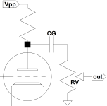
I want to check the value of the coupling capacitor needed for this schematic, with a 6SN7 with a plate resistor of 47K. The potentiometer in the image is actually a grid leak resistor of 220K.
I found this tool online: https://www.ampbooks.com/mobile/amplifier-calculators/coupling-capacitor/
I’m not sure what to use for “output impedance”, as the tube itself will be something like 7K.

I found this tool online: https://www.ampbooks.com/mobile/amplifier-calculators/coupling-capacitor/
I’m not sure what to use for “output impedance”, as the tube itself will be something like 7K.
Attachments
The formula is:
f = 1 / ( 2 x Pi x R x C ) ............ (where f is in Hz)
and C is the coupling capacitor ...........(in Farads)
and R = Rout + Rload ............. (where R is in Ohms)
where Rout is the output impedance of the triode stage (which includes the plate resistor, rp, and the cathode resistor)
and Rload is the 220k grid resistor.
Since the 220k grid resistor Rload is typically much larger than Rout,
you could neglect Rout and just use R = Rload (the 220k grid resistor), which would be close enough.
For your purposes, then the equation becomes: C = 1 / ( 2 x Pi x Rload x f )
where C is in Farads. To get the value of C in micro-farads, multiply the value in Farads by 1,000,000.

Hi Raymak,
I will try some calculations later.
With the online calculator the grid resistor makes a big difference in the frequency plot. This is quite different from what you say, that this value can be neglected. I don’t think both can be true, so what’s wrong with the online calculator?
Regards, Gerrit
I will try some calculations later.
With the online calculator the grid resistor makes a big difference in the frequency plot. This is quite different from what you say, that this value can be neglected. I don’t think both can be true, so what’s wrong with the online calculator?
Regards, Gerrit
It's the Rout that can be neglected, not the grid resistor Rload.
This is because Rout is only a few k ohms, while Rload is 220k ohms here.
So Rout would be about equal to the tolerance of the Rload resistor and so matters little.
The crossover frequency is inversely proportional to Rload for a given C.
And vice-versa.
This is because Rout is only a few k ohms, while Rload is 220k ohms here.
So Rout would be about equal to the tolerance of the Rload resistor and so matters little.
The crossover frequency is inversely proportional to Rload for a given C.
And vice-versa.