For replace the speaker protection relays and main switch on rear panel I have in the moment two different PA150B on the desk. I would like to use this opportunity to provide a description of early modifications I made to this model between 2003 and 2010.
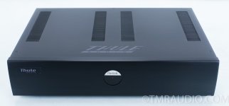
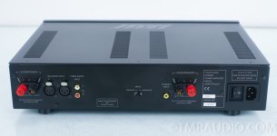
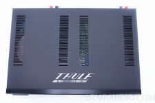
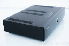
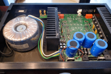
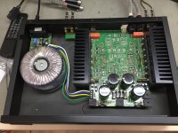
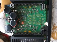
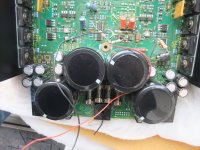
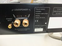
Outside images of this model with serial-No 2143031 (used main board EM1015 Rev7 or newer) are to find in image No 2-5 and No 7-9
In the attached schematic you will find also the preamp section - this means, it is the integrated amp version IA150B (EM1015, Rev0).
Unfortunately this schematic is not in all details identical to these devices of this model - but it is better than nothing.
I know two different PCB-versions, both with dual mono power supply (and both used for the integrated amp IA150B and power amp version PA150B) :
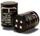
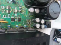
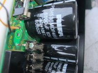
1) Mainboard EM1015 <rev.7 (offered 1997- 1999) for each channel with one BHC (Aerovox) T-Power elcap C25/C26 - go to image No 10 and No 11 and
https://www.dnm.co.uk/capbhc.html
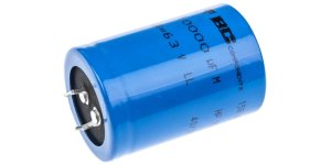
and one usual elcap 10.000uF/63V C27/C28 (image No 12) in the kind of this under
https://www.rs-online.vn/p/capacitor-snap-in-series-158-10000uf-63v/8773715/
so as voltage regulators LM317/337 in a SO-8 outline behind the voltage doubler circuit for the front end (differential amp + VAS) of power amplifier.
Basic description under
https://www.electronics-tutorials.ws/blog/voltage-multiplier-circuit.html
2) Mainboard EM1015 rev7 (offered after 1999) without BHC T-Power for C25/C26 instead this also only two usual (same) elcaps like C27/C28 (image No 12) in the kind of this:
https://www.rs-online.vn/p/capacitor-snap-in-series-158-10000uf-63v/8773715/
so as voltage regulators LM317/337, now in a TO220 instead the SO-8 outline used in the previous PCB versions
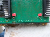
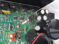
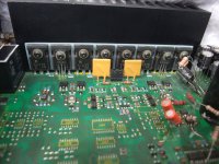
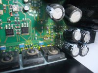
In both versions it is important to perform modification steps as follow in order to increasing reliability and reducing thermal stress as to see in image No: 6 around the mentioned voltage regulators - in the attached schematic (first image) Reg 7 - Reg 10
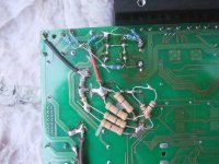
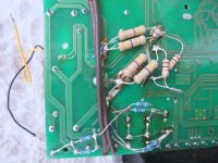
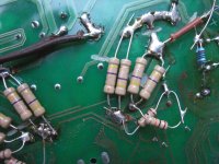
1) Removing the voltage doubler circuit for the front end completely (because no space present for voltage regulator heat sinks in necessary sizes).
more details and consequences are to read in post #13 under
https://www.diyaudio.com/community/threads/repair-thule-ia150b-no-sound-except-humming.303712/
BTW - this integrated amp from this topic use also the above mentioned main board versions.
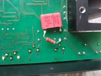
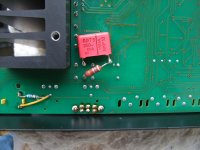
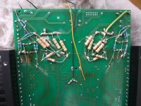
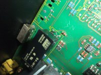
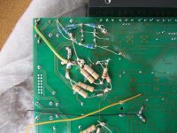
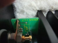
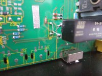
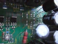
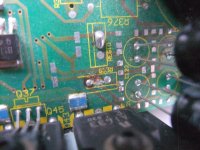
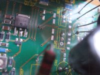
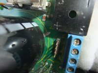
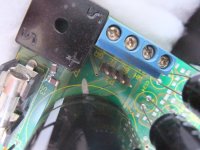
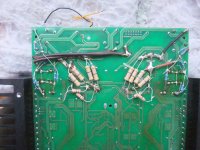
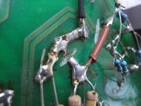
2) Introducing an additional zobel network before relay switch contact (image 13-15, R15/C57 so as R115/C157 in the attached schematic diagram) are in real live not in use and the already present zobel network R220/221 and C204/205 on main PCB are behind the relay contact and only in operation when the speaker relay is switched on.
The additional modification step, which I had perform on main board EM1015 <rev.7, is as follow:
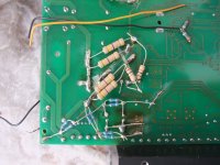
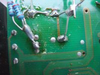
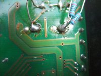
The BHC (Aerovox) T-Power elcap C25 and C26 was replace by the same usual elcap version as for C27 and C28. For getting similar sonic results as with BHC T-Power I introduce resistors 0R22 between C25 and C27 so as C26 and C28 (both in the "+" and the "-" rail) - check out images in post #2.
The main disadvantage of BHC T-Power caps was the very short life time. The excellent sonic performance with this caps was only present in the first few months of use and for this reason Thule Audio has decided to use usual Elcap versions from Rev. 7 onwards.
Outside images of this model with serial-No 2143031 (used main board EM1015 Rev7 or newer) are to find in image No 2-5 and No 7-9
In the attached schematic you will find also the preamp section - this means, it is the integrated amp version IA150B (EM1015, Rev0).
Unfortunately this schematic is not in all details identical to these devices of this model - but it is better than nothing.
I know two different PCB-versions, both with dual mono power supply (and both used for the integrated amp IA150B and power amp version PA150B) :
1) Mainboard EM1015 <rev.7 (offered 1997- 1999) for each channel with one BHC (Aerovox) T-Power elcap C25/C26 - go to image No 10 and No 11 and
https://www.dnm.co.uk/capbhc.html
and one usual elcap 10.000uF/63V C27/C28 (image No 12) in the kind of this under
https://www.rs-online.vn/p/capacitor-snap-in-series-158-10000uf-63v/8773715/
so as voltage regulators LM317/337 in a SO-8 outline behind the voltage doubler circuit for the front end (differential amp + VAS) of power amplifier.
Basic description under
https://www.electronics-tutorials.ws/blog/voltage-multiplier-circuit.html
2) Mainboard EM1015 rev7 (offered after 1999) without BHC T-Power for C25/C26 instead this also only two usual (same) elcaps like C27/C28 (image No 12) in the kind of this:
https://www.rs-online.vn/p/capacitor-snap-in-series-158-10000uf-63v/8773715/
so as voltage regulators LM317/337, now in a TO220 instead the SO-8 outline used in the previous PCB versions
In both versions it is important to perform modification steps as follow in order to increasing reliability and reducing thermal stress as to see in image No: 6 around the mentioned voltage regulators - in the attached schematic (first image) Reg 7 - Reg 10
1) Removing the voltage doubler circuit for the front end completely (because no space present for voltage regulator heat sinks in necessary sizes).
more details and consequences are to read in post #13 under
https://www.diyaudio.com/community/threads/repair-thule-ia150b-no-sound-except-humming.303712/
BTW - this integrated amp from this topic use also the above mentioned main board versions.
2) Introducing an additional zobel network before relay switch contact (image 13-15, R15/C57 so as R115/C157 in the attached schematic diagram) are in real live not in use and the already present zobel network R220/221 and C204/205 on main PCB are behind the relay contact and only in operation when the speaker relay is switched on.
The additional modification step, which I had perform on main board EM1015 <rev.7, is as follow:
The BHC (Aerovox) T-Power elcap C25 and C26 was replace by the same usual elcap version as for C27 and C28. For getting similar sonic results as with BHC T-Power I introduce resistors 0R22 between C25 and C27 so as C26 and C28 (both in the "+" and the "-" rail) - check out images in post #2.
The main disadvantage of BHC T-Power caps was the very short life time. The excellent sonic performance with this caps was only present in the first few months of use and for this reason Thule Audio has decided to use usual Elcap versions from Rev. 7 onwards.
Attachments
-
thule-audio_spirit_pa150b_sm.pdf216.5 KB · Views: 115
-
 PA150B EM1015 Rev8 2143031 front-II.jpg75.2 KB · Views: 115
 -
 PA150B EM1015 Rev8 2143031.jpg122.9 KB · Views: 79
 -
 PA150B-EM1015-Rev8-2143031-top.jpg210.7 KB · Views: 84
 -
 PA150B-EM1015-Rev8-2143031-front.jpg110.4 KB · Views: 87
 -
 EM1015 Rev8 burning PCB due thermal stress.jpg588.7 KB · Views: 103
 -
 PA150B EM1015 Rev8-I.png278.8 KB · Views: 165
 -
 PA150B EM1015 Rev8-II.jpg285.1 KB · Views: 114
 -
 PA150B EM1015 Rev8-III.jpg245.7 KB · Views: 119
 -
 BHC T-Power electrolytic capacitor.jpg21.1 KB · Views: 113
 -
 BHC T-Power electrolytic capacitor simplified schem.gif3.6 KB · Views: 108
 -
 BC 10000µF 63V.jpg54.4 KB · Views: 99
 -
 PA150B EM1015 Rev6-7 Ser.-No 2042013 addit.Zobel netw-III.JPG262.7 KB · Views: 94
 -
 PA150B EM1015 Rev6-7 Ser.-No 2042013 addit.Zobel netw-II.JPG347.6 KB · Views: 86
 -
 PA150B EM1015 Rev6-7 Ser.-No 2042013 addit.Zobel netw.JPG352.2 KB · Views: 91
Last edited:
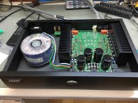
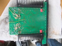
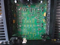
In the attachment here are to find the mods on the PA150B device with main board EM1015 Rev6-7, Ser.-No 2042013, which I have made several years ago.
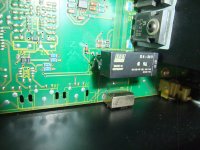
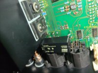
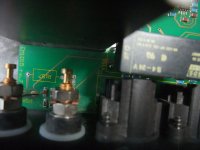
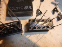
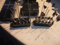
The currently work only concerns the replacement of the speaker protect relays by the type from the attached datasheet from SDS S4.
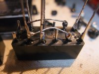
Because the coil connections have a predetermined polarity, the connection sequence had to be swapped for one relay - go to image No 12 and No 13.
The used main switch in poor quality wasn't replace. It was shorted by a wire due an exist outdoor switch with integrated inrush current limiter.
The currently work only concerns the replacement of the speaker protect relays by the type from the attached datasheet from SDS S4.
Because the coil connections have a predetermined polarity, the connection sequence had to be swapped for one relay - go to image No 12 and No 13.
The used main switch in poor quality wasn't replace. It was shorted by a wire due an exist outdoor switch with integrated inrush current limiter.
Attachments
-
 PA150B EM1015 Rev6-7 Ser.-No 2042013 BHC T-Power Replacement-III.JPG444.2 KB · Views: 60
 -
 PA150B EM1015 Rev6-7 Ser.-No 2042013 whole PCB.JPG456.6 KB · Views: 58
 -
SDS S Relays (2).pdf313.3 KB · Views: 35
-
 PA150B EM1015 Rev6-7 Ser.-No 2042013 SDS S4 24V.JPG543.7 KB · Views: 54
 -
 PA150B EM1015 Rev6-7 Ser.-No 2042013 SDS S4 24V-II.JPG540.3 KB · Views: 55
 -
 PA150B EM1015 Rev6-7 Ser.-No 2042013 SDS S4 24V-III.JPG506.2 KB · Views: 54
 -
 PA150B EM1015 Rev6-7 Ser.-No 2042013 BHC T-Power Replacement-II.JPG465.5 KB · Views: 52
 -
 PA150B EM1015 Rev6-7 Ser.-No 2042013 BHC T-Power Replacement.JPG433.5 KB · Views: 53
 -
 PA150B EM1015 Rev6-7 Ser.-No 2042013 TAKAMISAWA.JPG510.2 KB · Views: 56
 -
 PA150B EM1015 Rev6-7 Ser.-No 2042013 BHC T-Power Replacement-IV.JPG506.2 KB · Views: 63
 -
 PA150B EM1015 Rev6-7 Ser.-No 2042013 remov. volt. doubler-II.JPG548.2 KB · Views: 52
 -
 PA150B EM1015 Rev6-7 Ser.-No 2042013 remov. volt. doubler.JPG489.4 KB · Views: 55
 -
 PA150B EM1015 Rev6-7 Ser.-No 2042013 ROHM BjT's.JPG441.4 KB · Views: 57
 -
 PA150B EM1015 Rev6-7 Ser.-No 2042013 back panel.JPG300.2 KB · Views: 62
Last edited:
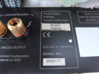
PA150B EM1015 rv.7 Ser.-No 9826177: Same mod steps than in post #2
The mentioned main board EM1015 from Ser.-No 2042013 in post #2 is below rv.7. (maybe rv.6 or rv.5)
Unfortunately the rv. No isn't to find on PCB (like rv.7 on image No 1+2 in this post)
The mentioned main board EM1015 from Ser.-No 2042013 in post #2 is below rv.7. (maybe rv.6 or rv.5)
Unfortunately the rv. No isn't to find on PCB (like rv.7 on image No 1+2 in this post)
Attachments
-
 PA150B EM1015 rv.7 9826177 PCB mark.JPG430.5 KB · Views: 38
 -
 PA150B EM1015 rv.7 9826177 PCB mark-II.JPG439.6 KB · Views: 36
 -
 PA150B EM1015 rv.7 9826177 PCB top view.JPG753.9 KB · Views: 34
 -
 PA150B EM1015 rv.7 9826177 rear panel.JPG601.1 KB · Views: 33
 -
 PA150B EM1015 rv.7 9826177 K1 speaker Rel.JPG641.8 KB · Views: 38
 -
 PA150B EM1015 rv.7 9826177 speaker rel prepared-I.JPG431.9 KB · Views: 38
 -
 PA150B EM1015 rv.7 9826177 speaker rel prepared-III.JPG412 KB · Views: 36
 -
 PA150B EM1015 rv.7 9826177 speaker rel prepared-II.JPG443 KB · Views: 40
 -
 PA150B EM1015 rv.7 9826177 mods-RIFA 6800-63.JPG453.1 KB · Views: 41
 -
 PA150B EM1015 rv.7 9826177 mods-16.JPG516.9 KB · Views: 42
 -
 PA150B EM1015 rv.7 9826177 mods-17.JPG631.1 KB · Views: 39
 -
 PA150B EM1015 rv.7 9826177 mods-XII.JPG652.8 KB · Views: 33
 -
 PA150B EM1015 rv.7 9826177 mods-X.JPG620 KB · Views: 40
 -
 PA150B EM1015 rv.7 9826177 mods-15.JPG459.7 KB · Views: 39
 -
 PA150B EM1015 rv.7 9826177 mods-14.JPG557.4 KB · Views: 48
 -
 PA150B EM1015 rv.7 9826177 mods-14.JPG557.4 KB · Views: 42
PA150B EM1015 rv.7 Ser.-No 9826177: Same mod steps than in post #2 - more images
Attachments
-
 PA150B EM1015 rv.7 9826177 mods-I.JPG598.9 KB · Views: 29
 -
 PA150B EM1015 rv.7 9826177 mods-II.JPG604.7 KB · Views: 25
 -
 PA150B EM1015 rv.7 9826177 mods-III.JPG624.7 KB · Views: 26
 -
 PA150B EM1015 rv.7 9826177 mods-IV.JPG621.3 KB · Views: 31
 -
 PA150B EM1015 rv.7 9826177 mods-V.JPG444.6 KB · Views: 29
 -
 PA150B EM1015 rv.7 9826177 mods-VI.JPG659.9 KB · Views: 27
 -
 PA150B EM1015 rv.7 9826177 mods-VII.JPG680.2 KB · Views: 25
 -
 PA150B EM1015 rv.7 9826177 mods-VIII.JPG637.9 KB · Views: 26
 -
 PA150B EM1015 rv.7 9826177 mods-IX.JPG695.6 KB · Views: 27