I have a couple of old PA amps that I would like to repurpose as 50W monoblocks.
The power supply uses a 370V secondary with two AX50s as a voltage doubler, so the unloaded EL34s have 830Vdc on the plate, falling to just under 800V when at maximum power, 70W for the PP pair. The voltage doubler also provides around 420V for the screen supply, from the non-doubled rectified output.
Does anyone here think it is ok to use modern tubes this way? I am thinking to replace the doubler with a straightforward FW rectified solution, so B+ would be around 420Vdc.
Annoyingly the EL34s are fitted with just 6mm between them so alternate tube options are severely limited. I had been thinking this was a job for an EL38.

I would replace the doubler, and maybe add a small fan.
Do you have a center tap on the HV winding?
Do you have a center tap on the HV winding?
370VAC sounds just about right for hifi amps with EL34, using SS or damper diodes as rectifiers. 800Vdc would probably kill modern tubes quickly.
The EL34 Spec Sheet mentions 800V as a maximum. However, the sample designs run between 250V and 400V, which seems more reasonable. Another problem is that the anode pin is right next to a heater pin, so going over 400V is risking a flash-over between pins (The reason why the 6L6 is limited to 400V while the otherwise identical 807 is rated for a maximum of 750V.)I have a couple of old PA amps that I would like to repurpose as 50W monoblocks.
The power supply uses a 370V secondary with two AX50s as a voltage doubler, so the unloaded EL34s have 830Vdc on the plate, falling to just under 800V when at maximum power, 70W for the PP pair. The voltage doubler also provides around 420V for the screen supply, from the non-doubled rectified output.
Does anyone here think it is ok to use modern tubes this way? I am thinking to replace the doubler with a straightforward FW rectified solution, so B+ would be around 420Vdc.
I wouldn't design for 800+ volts unless using xmtr power finals like the 814. Still, TV HD finals can do the same wattage at much lower voltages. The 6CB5 and 6LW6 can get you north of 100W at ~350V.
Here is the schema ...
There is an interesting automatic bias circuit that is worthy of another thread, which was discussed on UK Vintage Radio site: UKVR: Transformer coupled PP valves.

There is an interesting automatic bias circuit that is worthy of another thread, which was discussed on UK Vintage Radio site: UKVR: Transformer coupled PP valves.
Attachments
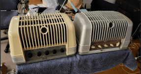
Didn't I see those amps for sale on Tradera recently?
I had one just like those 25 years ago, before I knew anything about tubes. I remember using a broom handle to activate the power switch...and to turn it of again seconds later after seeing blue flashes inside the rectifiers.
I had one just like those 25 years ago, before I knew anything about tubes. I remember using a broom handle to activate the power switch...and to turn it of again seconds later after seeing blue flashes inside the rectifiers.
I have a couple of old PA amps that I would like to repurpose as 50W monoblocks.
The power supply uses a 370V secondary with two AX50s as a voltage doubler, so the unloaded EL34s have 830Vdc on the plate, falling to just under 800V when at maximum power, 70W for the PP pair. The voltage doubler also provides around 420V for the screen supply, from the non-doubled rectified output.
Does anyone here think it is ok to use modern tubes this way? I am thinking to replace the doubler with a straightforward FW rectified solution, so B+ would be around 420Vdc.
Annoyingly the EL34s are fitted with just 6mm between them so alternate tube options are severely limited. I had been thinking this was a job for an EL38.
Way too high. 800V is the limit of EL34 plate. Simulate the load line and calculate one that works for you and stay below the max of EL34.
Use below link. The load line should stay below the max EL34 wattage dissipation curve all the way to ensure safety operation and long term stability.
EL38 sounds better to my ear comparing to EL34. But EL38 has much less power output comparing to EL34 unfortunately.
https://www.vtadiy.com/loadline-calculators/power-stage-calculator/
LOL! Yes, they are rather foreboding, and yes you are right, recently bought from Tradera.
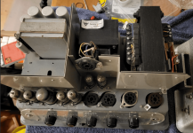
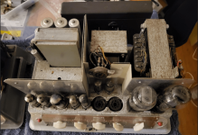
I did bring one up slowly on a Variac and it seemed OK. I shall post a picture of the underside at some point - not designed for ease of checking voltages.
I did bring one up slowly on a Variac and it seemed OK. I shall post a picture of the underside at some point - not designed for ease of checking voltages.
Philips EL6420, the service manual is available online.
With a little luck you can also find detailed information about how the transformers are wound, I found that information online for their baby brother EL6400.
With a little luck you can also find detailed information about how the transformers are wound, I found that information online for their baby brother EL6400.
The clever thing with these amps is that they adjust the bias automatically so they have a load line that hugs the max dissipation line on the characteristics graph. The output of the transformer between the cathodes is rectified and used to change the bias by 6Vdc.Simulate the load line and calculate one that works for you and stay below the max of EL34.
Someone was kind enough to post a link to the manual on that UKVR link above, and Tim Robbins kindly provided some missing details.Philips EL6420, the service manual is available online.
With a little luck you can also find detailed information about how the transformers are wound, I found that information online for their baby brother EL6400.
I did not expect them to be so challenging to make them useful. I will not perform any surgery on the chassis, I think that would make any sympathetic restoration pointless.
The bias scheme is indeed clever, but I wonder if it's really something to keep for hifi use.
The (black) transformers appear to be the same brand as those in my old 6400 amps, good power transformers but mediocre OPTs.
A bit of sand blasting and powder coating would count as skin care rather than surgery😎I will not perform any surgery on the chassis
The (black) transformers appear to be the same brand as those in my old 6400 amps, good power transformers but mediocre OPTs.
Many old PP amplifiers run really high plate voltage. My 1960 RCA 6550 monoblock puts 650V on 6550 plates too.My VTL ST85 tube amp runs 650V on the pp EL34s. Even that is quite high. But gives about 55-60 watts of power, I believe.
To my ears, most high plate voltage amps tend to sound better than common practice voltage (I.e. 350-500V for EL34, 6550, KT88 etc).
The Dynacord Eminent PA and guitar amps of the 70's ran a pair of EL34's at 750V on the anodes for around 80W output, I had one for a while, it had a pair of fat-bottle 6CA7's fitted.
You are beating them up with that kind of voltage.I have a couple of old PA amps that I would like to repurpose as 50W monoblocks.
The power supply uses a 370V secondary with two AX50s as a voltage doubler, so the unloaded EL34s have 830Vdc on the plate, falling to just under 800V when at maximum power, 70W for the PP pair. The voltage doubler also provides around 420V for the screen supply, from the non-doubled rectified output.
Does anyone here think it is ok to use modern tubes this way? I am thinking to replace the doubler with a straightforward FW rectified solution, so B+ would be around 420Vdc.
Annoyingly the EL34s are fitted with just 6mm between them so alternate tube options are severely limited. I had been thinking this was a job for an EL38.
I'm not sure what values T2 is, and though it's likely trivial resistance for some feedback, I also don't see the grid voltage anywhere mentioned. So I'm not sure what the bias is. There have been plenty of designs over the years that run tubes near, at, or above their posted Va values, but at a far lower than usual bias current, and with lower screen voltage. Resulting in tubes not dissipating more than acceptable, at idle. That is what this strikes me as. I'm curious what the supply voltage is like for the screens as well. Jack over at Electraprint did some work like this towards the end, I believe with pp as well as se designs. Someone will remember the name he gave to it, but he raved about the sound quality, as well as the amount of power produced. Others have done it as well, I've seen the 25w pp el-84 amps, etc. Not saying it's ok for the tubes, I've never studied it. But I know some people who knew far more than I who obviously swore by this. I mean, what if it is shorter tube life. Not like they just get killed right away, and this hobby is all about trade-offs. Making power for a PA system was also about trade offs, not to mention how much cheaper tubes were.
Loren
Loren
- Home
- Amplifiers
- Tubes / Valves
- EL34s - is 800VDC too much?