I have a Soundscraftmen RA 7502, just given to me by a friend. He has not powered it up for years.
The A channel Looks OK, but the B channel has 800 mV Dc offset on the output. It will pass a 1K sine wave AOK, but rides on the DC offset
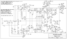
I am just starting to dig into it, and find that info is hard to find. Nothing on hifiengine. I found a blurry schematic on AudioKarma (attached)
Are there any Soundcraftsmen Gurus out there who have literature? Schematics, layouts, service manual?
F
The A channel Looks OK, but the B channel has 800 mV Dc offset on the output. It will pass a 1K sine wave AOK, but rides on the DC offset
I am just starting to dig into it, and find that info is hard to find. Nothing on hifiengine. I found a blurry schematic on AudioKarma (attached)
Are there any Soundcraftsmen Gurus out there who have literature? Schematics, layouts, service manual?
F
Attachments

This cap? Its a 220uF Electrolytic on the board.
F
Back story: My buddy Chris bought this amp approx 1990. We saw it in a repair shop in Torrance, CA. He has had it since then. He ran it with a pair of homemade D'Appolito speakers and it kicked ***. He is downsizing and just gave me the amp AND the speakers.
Yep, the LEDs are super cool.
F
Back story: My buddy Chris bought this amp approx 1990. We saw it in a repair shop in Torrance, CA. He has had it since then. He ran it with a pair of homemade D'Appolito speakers and it kicked ***. He is downsizing and just gave me the amp AND the speakers.
Yep, the LEDs are super cool.
Attachments
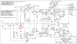
Yup , that one (DC cap). Get a nice Nichicon "muse" 220NP @ 35-50V. 10uF /35 muse for C1.This cap? Its a 220uF Electrolytic on the board.
C4 - 47pF , get a nice silver mica 300-500V. C4 is the main compensation cap that keeps it stable ! (VAS --- lead comp.)
All the other small caps , keep the ceramic/mylar's - they don't wear out.
All the others .... C7, C10-12 , C18 , go up in voltage , if possible.
The two monster caps (supply = 10Kuf +++), at least test them for leakage/ESR.
Re-grease the big TO-3 trannies , at least check to see if the white grease is dry/chalky. Amp should last another 25 years.
PS - I did a 1990 amp with similar components , ALL the caps were either total failure or way off ESR. Even some of the old ceramic disks.
Ceramic disks are just way off natively , they don't usually degrade.
OS
I agree with suspicion of C6. A more exacting way to test is to measure DC voltage drop across R10. Any voltage present across R10 is almost certainly leakage current through C6 and will amplified by the ratio of R9/R10 and contribute an added offset error across R9. Other contributors to amp output voltage are base bias drops across R3+R4 and across R9, plus the voltage offset error of the Q1,Q2 differential stage.
If offset error remains unexplained, measuring bias voltages with respect to ground can help reveal the bias picture, i.e.
voltages at bases of Q1 and Q2, amp output voltage, and junction of C6,R10.
If offset error remains unexplained, measuring bias voltages with respect to ground can help reveal the bias picture, i.e.
voltages at bases of Q1 and Q2, amp output voltage, and junction of C6,R10.
Rayma, ostripper and BSST,
Thanks so much for the schematics and suggestions.
1. I replaced the 220uF C5(as noted on correct schematic). Offset unchanged.
2. I probed voltages and calculated currents in the diff pair and the following stages, noted on the attached schematic. I don't know what they should be, but nothing seemed to be "broken" to me. The forward voltage on the CR3+CR4 pair seems OK at 1.253V
3. While probing R9, everything went haywire - the power supply started clicking on/off. I have the amp on a dim bulb tester and and the dim bulbs never lit, just pulsed when the PS clicked in. R9 looked a little damaged so I replaced it, and ..... no improvement in offset. Maybe there was a cold solder joint that I wigggled. After replacing R9 the power supply seems stable now. It takes a second or so to kick in, and stays on. I don't understand the protection circuits in this amp yet...
4. I have not measured any resistor values yet. My repair experience so far is with Hafler and Leach amps. These amps have fully complimentary input stages and offset problems have ALWAYS been caused by the resistors or diodes that set the bias currents for the diff amps.
Please take a look at my measurements noted on the schematic and see if anything looks off to you guys.
ANY IDEAS before I start measuring a bunch of resistor values?
How do I check Bias current?
Fisher in Alabama
Attachments
Probing the base of Q2 (which is one end of R9) while powered could certainly cause glitches.
Output bias current is set by pot R17, but there is no stated procedure.
Output bias current is set by pot R17, but there is no stated procedure.
Hi Fisher,
About your measurements:
Re Q3 current, I believe you may have bumped a decimal point. I take current to be 0.675V/390 ohm = ~1.7mA rather than 17mA. The 1.7mA seems reasonable.
The Q1 base current seems reasonable--- 0.237/(68k+1k) = 3.4uA; offset error in the diff pair is (0.242 - 0.232) - ~ 10mV, so not bad. But the apparent bias across R9 looks way off: +0.69- (-0.232) =0.922V; 0.922V/22k = 42uA. I assume you found no significant DC across R10. You mentioned having replaced R9. R10 value is suspect; if it went way up in resistance, that could explain the elevated voltage, so it deserves checking. The other big suspect is degraded hfe in Q2.
Do you have a transistor checker? Or you could exchange Q1 and Q2 to see if offset changes. Or replace both input transistors.
Good luck!
BSST: Good suggestions, I do have one those Peak transistor checkers. Will check them soon.
I got distracted by the power supply protection behavior - The PS now continuously cycles into protection mode. Not sure what I did. The problem is in the B channel. The PS does not go into protection mode when I unplug power to the B channel board.
Can you explain the protection circuit? I have been studying it, but not sure. Looks like Q21 and Q26 will be turned on when the current in the emitter resistors R63 and R67 exceeds some threshold. And this triggers the protection?
I have no load on the outputs right now, so there should not be any current through the emitter resistors.
Does anything else trigger the protection?
... and "whoo-eee" the protection op-amps run on 12 VDC RELATIVE TO THE -93 RAIL***. I haven't been bit by this amp, but probing that circuit is frightening. Dr Leach told me years ago - use one hand only when working on these high voltage power amps.
Fisher
UPDATE ON THIS PROJECT:
1. I tested Q1 and Q2.
Q1: HFE=135
Q2: HFE=49
So I replaced them with a couple of transistors left from a Hafler project: 2N5550. I sorted them to find matched Betas of 165
2. Then the B channel started sending the power supply into protection. The click-on-click-off pattern. After a lot of study and investigation, I found one shorted output transistor: Q13. I removed this transistor since it is in parallel with 2 other transistors.
Now the amp works! DC offset is: +23 mV Chan A, -44mV Chan B
I have done some google searching for a replacement transistor. Looks like it is out of production. A bunch of EBay sellers have the transistor. I am wary of counterfeits.
Question for the experts:
1. How should I source a replacement output transistor? I am presuming the 3 output transistors in parallel should be matched.
2. Is there a recommended replacement for Q1&Q2? the original is a MMPSL01
Fisher
- Home
- Amplifiers
- Solid State
- Soundcraftsmen RA7502 - Looking for info