After a few years of solid state RF diversion, I found myself missing the difficulty and inconvenience of vacuum tubes.
As a get back into it warm up, I thought a small utility amplifier similar to the one in this thread ( that also generated the DHT SSE ):
https://www.diyaudio.com/community/threads/tubelab-se-removing-mosfets.291593/
but built on a 3D printed chassis, instead of a cake pan, could be useful to me. It won’t need to be much of an amplifier - it will join the kitchen table lineup at my lake house and provide some tube audio sound for the second generation of RF stuff, while also providing a low current, tube voltage, power supply if / when needed.
If 3D printing a chassis proves to be a viable means of constructing a tube amplifier, then I might go further forward with the DHT SSE project that started the original thread (now time locked) on this subject, but a more likely end point would be a 3D printed chassis for my existing DHT SSE.
Since this is the TubeLab forum, the objective is a low power / low heat SSE monoblock, while also exploring what will, or what won’t, work in terms of construction on a 3D printed chassis.
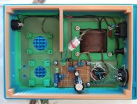
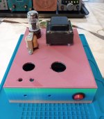
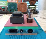
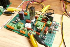
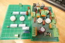
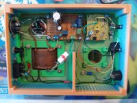
I already have a chassis printed up, and a working power supply completed. The power transformer is a $1 hamfest scrounge, that on the line voltage here at the lake outputs 230-0-230 and 7.2 volts on the filament winding. It is mounted above the chassis by the width of a #8 nut and a second 3D printed washer so that air can flow around it for cooling and minimize heat transfer to the plastic. The chassis is beefed up a bit in this area to support the weight of the transformer.
The rectifier tube is a 6X5. This tube was selected because, AFAIK, it has the lowest voltage drop ( 22 volts ) of any of the common 6 volt rectifier tubes; despite its somewhat poor reputation, this type has worked flawlessly in the utility amplifier in the ham shack.
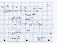
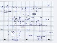
The power supply is a generic CLC circuit, with a 150K bleeder, and a Hammond 154M 2H choke. The input cap is 4.7 uF and the out cap is 100 uF. The secondary of the power transformer has pretty high resistance - about 190R / leg, so I did not add any series resistance between the transformer and the tube.
Each filament line has a 0R5 resistor in series to drop the filament voltage to an acceptable level. The string is elevated to 1/6th the B+ voltage by a 150K/27K voltage divider.
All power supply voltages are available at the rear panel octal socket. The output voltage ( loaded by the bleeder and the elevator divider ) is 300 VDC. The filament voltage under the 6X5 load is 6.4 volts. The 6X5 data sheet indicates I should get 250 volts up to about 55 mils. Based on prior experience, that will be pretty marginal for the CCS loaded 12AT7 front end, so some improvisation may be needed here. PSUD, which takes into account some of the resistances, is less optimistic.
(Most of ) the wiring is some stiff teflon insulated stuff that I got at a hamfest. The other parts are cheap generic AliExpress stuff. The metal frames / socket parts are daisy chain grounded to the safety ground for (some) shock protection.
The chassis is surprisingly rigid, much more so than most of the inexpensive aluminum chassis. Better than a cake pan for sure. The .stl is attached.
So far, so good. It has been burning in for a few days, but without any load, no real heat is being generated.
As a get back into it warm up, I thought a small utility amplifier similar to the one in this thread ( that also generated the DHT SSE ):
https://www.diyaudio.com/community/threads/tubelab-se-removing-mosfets.291593/
but built on a 3D printed chassis, instead of a cake pan, could be useful to me. It won’t need to be much of an amplifier - it will join the kitchen table lineup at my lake house and provide some tube audio sound for the second generation of RF stuff, while also providing a low current, tube voltage, power supply if / when needed.
If 3D printing a chassis proves to be a viable means of constructing a tube amplifier, then I might go further forward with the DHT SSE project that started the original thread (now time locked) on this subject, but a more likely end point would be a 3D printed chassis for my existing DHT SSE.
Since this is the TubeLab forum, the objective is a low power / low heat SSE monoblock, while also exploring what will, or what won’t, work in terms of construction on a 3D printed chassis.
I already have a chassis printed up, and a working power supply completed. The power transformer is a $1 hamfest scrounge, that on the line voltage here at the lake outputs 230-0-230 and 7.2 volts on the filament winding. It is mounted above the chassis by the width of a #8 nut and a second 3D printed washer so that air can flow around it for cooling and minimize heat transfer to the plastic. The chassis is beefed up a bit in this area to support the weight of the transformer.
The rectifier tube is a 6X5. This tube was selected because, AFAIK, it has the lowest voltage drop ( 22 volts ) of any of the common 6 volt rectifier tubes; despite its somewhat poor reputation, this type has worked flawlessly in the utility amplifier in the ham shack.
The power supply is a generic CLC circuit, with a 150K bleeder, and a Hammond 154M 2H choke. The input cap is 4.7 uF and the out cap is 100 uF. The secondary of the power transformer has pretty high resistance - about 190R / leg, so I did not add any series resistance between the transformer and the tube.
Each filament line has a 0R5 resistor in series to drop the filament voltage to an acceptable level. The string is elevated to 1/6th the B+ voltage by a 150K/27K voltage divider.
All power supply voltages are available at the rear panel octal socket. The output voltage ( loaded by the bleeder and the elevator divider ) is 300 VDC. The filament voltage under the 6X5 load is 6.4 volts. The 6X5 data sheet indicates I should get 250 volts up to about 55 mils. Based on prior experience, that will be pretty marginal for the CCS loaded 12AT7 front end, so some improvisation may be needed here. PSUD, which takes into account some of the resistances, is less optimistic.
(Most of ) the wiring is some stiff teflon insulated stuff that I got at a hamfest. The other parts are cheap generic AliExpress stuff. The metal frames / socket parts are daisy chain grounded to the safety ground for (some) shock protection.
The chassis is surprisingly rigid, much more so than most of the inexpensive aluminum chassis. Better than a cake pan for sure. The .stl is attached.
So far, so good. It has been burning in for a few days, but without any load, no real heat is being generated.
Win W5JAG
edit: the original thread on this subject: https://www.diyaudio.com/community/threads/3d-printed-sse-parts-and-another-dh-sse.361798/
Attachments
Last edited:

It looks like I need 33-36 dB overall gain from line input to speaker output to substitute for, or replace, the integrated circuits that I typically use as audio outputs in my homemade stuff.
I can't help but notice that the 5842 has a maximum plate voltage rating of 200 VDC, and a mu of 40-44. Has anyone (George?) measured the actual stage gain of the TSE front end? I never measured it on my TSE, probably because I was too busy hacking oddball output tubes into it. My recollection is that the sweet spot on the 5842 was about 175 VDC on the plate.
I'm guessing that the CCS load brings the actual stage gain pretty close to the mu of the tube, but as little as 23 to 25 dB actual gain would be OK I think, because I could always use a high gain output like a 6CL6, 6GK6, or 6BQ5 as the power stage, to make up the difference.
Win W5JAG
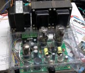
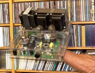
The very first TSE was built in a clear Lexan case. It is still as quiet as it ever was. Note that polycarbonate (Lexan) does OK with 300B's and a 5AR4 in close proximity. The cheap plastic I got from Home Depot back in 2005 when I built it did not like the heat with the weight of three transformers on its back. One must always connect the transformer housings and circuit ground to power line (mains) ground. Leakage current from winding to shell are possible, and it actually happened in this amp due to water exposure from Hurricane Wilma.Plastic case means no screening and no earthing of case. Not my preference for a tube amp…
I never measured the exact gain, but the design criteria was that I had to be able to drive it to clipping from an iPOD or cell phone with any of the three popular output tubes in place. That was the limiting factor during my search for a suitable driver tube. My collection of Raytheon 5842's seem to like about 175 volts on the plate. Genuine WE 417A's prefer about 150 volts and some of them can produce very low THD numbers, like 0.15%.
If you are perf boarding your amp like shown in your power supply, then you are free to choose any driver tube you want. Since the TSE was designed the WE417A's have vanished, and 5842's are no longer $4. I am now looking at a new and slightly more complicated driver design for UNSET-II and possibly TSE-III. These experiments have revealed large voltage gains at very low THD from many of the 6AU6 pinout compatible 7 pin tubes, as well as the 6EJ7 compatible 9 pin TV IF amp tubes.
Some info can be found starting in post #110 here:
https://www.diyaudio.com/community/...he-way-i-always-wanted-to-do-it.410333/page-6
Simulated circuit is included. Some experimentation with component values will be needed for each application as this can be set for "plenty of clean gain" or "extreme but somewhat nasty gain." Values will also depend on the tube choice, but I have a list of about 15 different tube numbers that work well in both 7 pin and 9 pin flavors. There are two parallel wired tube sockets on my DEV board. Only one tube is used at a time.
Attachments
Last edited:
Hi George,
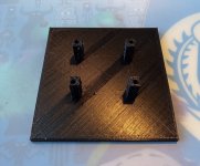
I have some cheap prototyping perf boards that take a single 7/9 pin socket, or an octal socket, that I plan on trying out. They are not very big, about 40 x 40 mm IIRC, and the mounting posts I made take up a fair amount of the available space. I don't know if they will be usable for this purpose or not. I don't have any here at the office to shoot a pic of. Molding the mounting posts into the "chassis" obviously is a space waster, but is convenient. It works fine for solid state stuff. I suspect it will not be strong enough for tube insertion unless it is supported underneath at the time. Extraction should be OK.
I'm not real satisfied with the power transformer grounding. This one has some type of rubbery insulators on both sides of the mounting bolts that would prevent it from being at chassis ground even on a metal chassis. I believe the transformer came from a Knight R-55 receiver. I'm thinking a printed transformer cover is probably going to be required here. Otherwise, everything that is metallic that can be touched is at safety ground.
I had circuit ground at safety ground and then removed it ( for some reason ), so I'll put that back.
I fear voltage is my big limitation. I seem to recall seeing something on your website about the totem pole configuration being a step to the CCS loaded driver tube, but for the life of me I cannot find it now. Playing around with TubeCad suggests that a usable totem pole can be made at less than 250 volts with 5 ma on the plate of a 12AT7 with good gain. A 12AU7 has about 10 dB less. Voltage swing is constricted on both, but I think it will be enough.
I have a lifetime supply of 5842; actually considerably more than a lifetime at this point. I'm leaning toward that tube to start, but this thing should lend itself to a lot of experimentation and trial and error.
Win W5JAG
Attachments
I have a box with about 12 to 15 Raytheon 5842's that are all pulls from some surplus equipment. They all seem to work fine in a TSE. One of the most common requests I hear is for a TSE type design that uses a more common driver tube. The 5842 seems to be rather scarce in most of the world other than the US. It also has a weird pinout making substitutions non trivial in a PC board based amp.I have a lifetime supply of 5842; actually considerably more than a lifetime at this point. I'm leaning toward that tube to start, but this thing should lend itself to a lot of experimentation and trial and error.
A CCS loaded triode needs to have lots of Gm and a Mu of 40+ to get enough gain to push a DHT into clipping from an iPhone (yes people do this). This rules out many tubes. For unknown reasons many people regard the 12AX7, 12AT7 and 12AU7 tubes as "guitar amp tubes" which have no place in a true HiFi amp.
The UNSETURATOR design that I showed in post #4 was actually an experiment INTENDED for a guitar amp. The Saturator (Gyrator loaded pentode) was first used as the input stage in a small guitar amp, and so named since a typical electric guitar can drive it to fully saturated square waves at about half throttle. I combined that with an UNSET input design and used pots for nearly every resistor. Once I started turning knobs, I was quite surprised at the large number of different tubes that made excellent, very clean numbers as driver circuit. One cheap unknown tube gave me over 50 volts RMS at 0.07% to 0.11% THD (4 samples) which is barely above my measurement threshold of 0.03% with the audio oscillator plugged into the audio analyzer.
When I was playing with TubeCad, the 12AX7 did look a lot easier to implement at the lowish voltages I will probably be stuck with. But then I thought of the 5842.
I can't recall what the single triode version of the 12AX7 is: 6AT6? 6AV6?
Most of my tubes are out in my warehouse of junk, but the tube inventory has gotten stuck behind so much new junk it's almost impossible to get tubes from there. Last week I spent fifteen minutes crawling over and through stuff just to get an old Shuguang coke bottle 6L6. But I was able to find ten Raytheon 5842 here at the office.
Another objective of this exercise is to see how well, if at all, I can measure a small tube amp with that equipment I've been using up at the lake for simple RF.
Win W5JAG
The 6AV6 is 1/2 of a 12AX7 with a pair of diodes. The 6AT6 is similar but has a Mu of 70. The 6C4 is 1/2 of a 12AU7 and the 6AB4 is half of a 12AT7. The 6AQ6 is a low heater power version of the 6AT6.I can't recall what the single triode version of the 12AX7 is: 6AT6? 6AV6?
Last edited:
The 5842 seems to be rather scarce in most of the world other than the US. It also has a weird pinout making substitutions non trivial in a PC board based amp.
And, the Russian tube that is touted as a substitute, 6C45, also looks to have sky rocketed in price - barely cheaper, if at all, than 5842 and mostly unavailable here in the states. I thought I might get a couple of those to play with, but I'm less sure now after pricing them, especially when there are so many other tubes to play with.
If the little proto pcb's I have will work, swapping entire circuit blocks should just take a screwdriver to remove one board and install another.
I'm debating whether or not I should install an adjustable negative supply - I don't see that I need it for this project, but it might be handy to have at the rear socket for the future; the parts are on hand.
After looking at your dev board, I'm embarrassed to say that after cutting chunks out of an SSE board, it literally never occurred to me to just bend the pins on a socket to install it on an ordinary perf board.
Unfortunately it may be a few weeks before I get to actually do anything - I'm super far behind at work.
Win W5JAG
Last edited:
I use the cheap G-10 / FR4 perf boards from Amazon that have a grid of plated through holes on 0.1 inch spacing. Most of them will need to be drilled out a bit to accept tube socket pins, especially octal. Amazon also sells cheaper boards that have a plated ring around the hole on one side only. They come in several sizes. I have found valid uses for both. The single sided ones are easier to use with tube sockets but it's easier to rip the pad off if only a wire is soldered to it. The double sided boards work best with high density wiring around IC chips.After looking at your dev board, I'm embarrassed to say that after cutting chunks out of an SSE board, it literally never occurred to me to just bend the pins on a socket to install it on an ordinary perf board.
Attachments
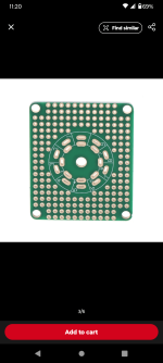
As a start, these are what I am going to try to make work.
There used to be an octal version, but it seems to be no longer available. I have a half dozen or so of each to play with.
It's nice that they provide the hole for the obligatory LED light. Which I used to think was cheesy, but now kind of like ...
Win W5JAG
There used to be an octal version, but it seems to be no longer available. I have a half dozen or so of each to play with.
It's nice that they provide the hole for the obligatory LED light. Which I used to think was cheesy, but now kind of like ...
Win W5JAG
Attachments
I finally got some free time to work on this.
First, I reconnected the circuit ground to the safety ( AC mains ) ground.
After that, everything went sideways.
My plan was to use a 5842 for the front end, however, the 9 pin tube sockets I had with me are different from the sockets I have back at home base, and, of course, they are just enough wider than the other sockets to not fit the printed hole in the chassis.
I had exactly two 7 pin sockets here, and just one 7 pin tube, which in an uncharacteristic moment of good luck, turned out to be a Tung Sol 6AB4.
I installed the socket unto one of the prototype pc boards, intending to use through hole components, but changed my mind and thought it might be informative to use SMD parts. Ordinarily, SMD parts would have been much easier to install, but since the tube socket was already in place, this became a time consuming royal pain in the a** unless I wanted to use the top of the board. Which I did not. So I didn’t. Since I managed to confuse the cathode and grid pin, once I finally had that part of the board wired, I had to take it all apart and do it over.
I was using Kester lead free solder and I hate it. It has some silver content, but it is definitely crap compared to regular silver solder. The joints look like crap. Also, I used 1206 parts. I’m not really a fan of 1206. When I was first counseled to make the switch to SMD, I bought a lot of 1206 parts because they didn’t look as impossibly small as some of the other sizes. After using them for a bit, they are actually too big - the smaller sizes are easier ( I think ) to work with. 1206 is sort of the SMD analog to 1/4 watt through hole, and I was not sure the smaller parts would work here.
The 10M45 is also in the SMD format. I did not have any caps that I felt could take the plate voltage without smoking, so the output cap is through hole.
When I hooked it up to power, it drew about 11 ma which seemed okay, until I figured out the 10M45 was wired wrong. Which meant more rework.
Eventually, I got everything right. Probably. I haven’t actually put any signal through it, because I was afraid that the way things were going, I would wind up frying test equipment.
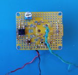
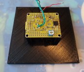
It lights up. It has reasonably correct looking voltages at the pins where they would be expected. It draws current, so, it ought to work. Layout is not that great, but probably okay.
The circuit is the SSE front end with some immaterial component value changes. The grid resistor is 200K instead of 220K, because I didn’t have any 220K in 1206 SMD. I used a 220R resistor in series with the grid, which is probably not needed at all, but does not hurt anything. The out cap is 100 nF instead of 220 nF. In what might be a consequential deviation, stead of a 1500 uF electrolytic bypass, I used a 100 uF non polarized ceramic capacitor. In an abundance of caution, I used an input cap, a 470 nF ceramic capacitor. I will probably remove this or replace it with something better at some point.
Instead of a fixed 330 ohm current set resistor, I used a 1K pot. Current draw is adjustable from about 4 ma to about 11 ma. I tacked a 220K resistor across the output as a temporary load.
Right now I have the grid set for 1.5 volts. This is 6.9 ma current draw and sets the plate voltage at 184 VDC. The B+ rail is now 282 VDC under this light additional load.
The SMD 10M45 gets pretty warm. Possibly too warm. Time will tell.
First, I reconnected the circuit ground to the safety ( AC mains ) ground.
After that, everything went sideways.
My plan was to use a 5842 for the front end, however, the 9 pin tube sockets I had with me are different from the sockets I have back at home base, and, of course, they are just enough wider than the other sockets to not fit the printed hole in the chassis.
I had exactly two 7 pin sockets here, and just one 7 pin tube, which in an uncharacteristic moment of good luck, turned out to be a Tung Sol 6AB4.
I installed the socket unto one of the prototype pc boards, intending to use through hole components, but changed my mind and thought it might be informative to use SMD parts. Ordinarily, SMD parts would have been much easier to install, but since the tube socket was already in place, this became a time consuming royal pain in the a** unless I wanted to use the top of the board. Which I did not. So I didn’t. Since I managed to confuse the cathode and grid pin, once I finally had that part of the board wired, I had to take it all apart and do it over.
I was using Kester lead free solder and I hate it. It has some silver content, but it is definitely crap compared to regular silver solder. The joints look like crap. Also, I used 1206 parts. I’m not really a fan of 1206. When I was first counseled to make the switch to SMD, I bought a lot of 1206 parts because they didn’t look as impossibly small as some of the other sizes. After using them for a bit, they are actually too big - the smaller sizes are easier ( I think ) to work with. 1206 is sort of the SMD analog to 1/4 watt through hole, and I was not sure the smaller parts would work here.
The 10M45 is also in the SMD format. I did not have any caps that I felt could take the plate voltage without smoking, so the output cap is through hole.
When I hooked it up to power, it drew about 11 ma which seemed okay, until I figured out the 10M45 was wired wrong. Which meant more rework.
Eventually, I got everything right. Probably. I haven’t actually put any signal through it, because I was afraid that the way things were going, I would wind up frying test equipment.
It lights up. It has reasonably correct looking voltages at the pins where they would be expected. It draws current, so, it ought to work. Layout is not that great, but probably okay.
The circuit is the SSE front end with some immaterial component value changes. The grid resistor is 200K instead of 220K, because I didn’t have any 220K in 1206 SMD. I used a 220R resistor in series with the grid, which is probably not needed at all, but does not hurt anything. The out cap is 100 nF instead of 220 nF. In what might be a consequential deviation, stead of a 1500 uF electrolytic bypass, I used a 100 uF non polarized ceramic capacitor. In an abundance of caution, I used an input cap, a 470 nF ceramic capacitor. I will probably remove this or replace it with something better at some point.
Instead of a fixed 330 ohm current set resistor, I used a 1K pot. Current draw is adjustable from about 4 ma to about 11 ma. I tacked a 220K resistor across the output as a temporary load.
Right now I have the grid set for 1.5 volts. This is 6.9 ma current draw and sets the plate voltage at 184 VDC. The B+ rail is now 282 VDC under this light additional load.
The SMD 10M45 gets pretty warm. Possibly too warm. Time will tell.
Win W5JAG
Attachments
I put two red LEDs and a resistor in series across the 2.2K ohm screen resistor in output stage of the little 4 tube push pull guitar amp that I built a few years ago. They give a visible indication of screen grid abuse before the glowing grid wires do. Despite violating nearly every spec in the data sheet the original tubes are still in the amp. I guess 32ET5's can't manage to blow themselves up on 170 volts of B+. It's likely that the 3.2 watt heater can't make enough emission to melt anything. The most power I can squeeze out of a pair on 170 volts is just under 4 watts. The 50B5 / 50C5 tubes with their 7.5 watt heater can produce 20 watts from a pair, though 340 volts was used to get there. It's also quite easy to melt one at this level, but nothing beats the 6AQ5 for meltability. The glass is just too close to the plate and most 6AQ5's are misaligned enough to hotspot. Some will develop a red spot even while operated within the ratings.It's nice that they provide the hole for the obligatory LED light. Which I used to think was cheesy, but now kind of like ...
You will know it's too hot when it unsolders itself and falls off. I made a little RF power amp for 2 watts on 902 MHZ many years ago and was feeding the 3.6 volt cell phone chip amp 5 volts. I wound up soldering a U shaped piece of copper flashing to the back side of the perf board after filling all of the holes under the chip with solder. That was enough for the board to work. It's still alive in a box somewhere in my junk collection.The SMD 10M45 gets pretty warm. Possibly too warm. Time will tell.
I made a jig to hold these boards during construction with or without a tube socket installed. If I had sense enough to do this yesterday, it would have saved me at least a couple of hours of time and quite a bit of frustration. It should also be useful for testing to keep it from just flopping around on my solder mat.
I found one of the correct nine pin sockets here, so I'm thinking of stripping this board back down and maybe using it for the power amplifier. Probably not a 6AQ5, though - I am going to try to avoid melting stuff with this project. The 6G6 worked well in the other utility amp, so I might use a pentode connected 6AK6 in this one.
I'd like to work on it some more today, but I am also behind on mowing so I will probably have to go back home. I am also way behind on film developing - I probably have six or seven rolls I need to do.
Win W5JAG
edit: fwiw these boards are 40 x 48 mm.
Attachments
Last edited:
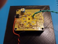
Even a simple tool can make a significant difference. With something to hold the board in a fixed position, I was able to rework it in less than an hour from getting tools and parts out to having everything put back away.
The rework puts the input and output at opposite ends of the board, pretty much as far apart as is possible on this board. The old output cap is now the input cap, the 470 nF ceramic is in the kitchen trash. I added another 100 nF film cap for the new output. I cut the lead length of the wiring around the 10M45 by half or more.
I used a hot air gun to remove parts from the pc board and thought this might damage the stand, but it did not.
Attachments

Last edited:
Where did you get your protype boards? The hole spacing looks very nice compared to the miniature ones normally available.
I order them from AliExpress. There are several different types of prototype boards with tube sockets of varying sizes embedded in them.
They seem to be good quality boards - plated through holes. I didn't damage it with the hot air gun or by yanking heated leads out of the plated holes.
Prices seem to have gone up since I last bought some, unfortunately.
Win W5JAG
They seem to be good quality boards - plated through holes. I didn't damage it with the hot air gun or by yanking heated leads out of the plated holes.
Prices seem to have gone up since I last bought some, unfortunately.
Win W5JAG
So, on a preliminary basis, it does appear to work.
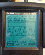
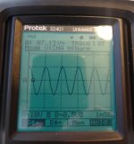
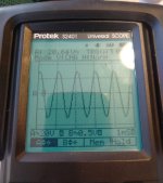
With 1 volt peak to peak 1 Khz sine wave input, output is 20 volt peak to peak with a 6C4 tube. This is 26 dB gain.
With 1 volt peak to peak 1 Khz sine wave input, output is 50 volt peak to peak with a 6AB4 tube. This is 34 dB gain.
Both tubes look to handle 2 volt peak to peak without clipping; the lower gain 6C4 can go well beyond that.
Attachments

Last edited:
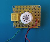
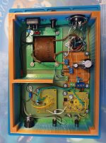
I mounted the driver board and have the rest of the chassis mostly wired up, ready to drop in a power amp board.
I'm not crazy about the output transformer because of the exposed lugs that carry B+ level voltage. They are insulated with some heat shrink, but I think it would be prudent to change it out for something that has leads. It was the only suitable transformer I had with me.
These are not very heavy transformers, but the chassis has no problem supporting them. It remains very rigid - as good as the Hammond aluminum chassis I have used in other builds, I think.
It has been sitting with power applied for most of the afternoon with a scope on the output. It seems stable so far. If I make it up here next weekend, I'll try to remember to bring a better scope.
Attachments
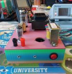
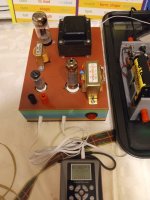
This is a working test amp - this first tube lineup is 6C4 driver, and 6BQ5 power amplifier. It has been running without issue all day, driven by the headphone output of an MP3 player, while I developed film, except for a few minutes mid afternoon when I installed the bottom cover.
The B+ is setting lower than I expected, and my expectations were pretty low to start with - it is 220 VDC under load. The 6BQ5 is triode wired for simplicity and on the 7K tap. I guesstimated about 200R for the cathode resistor, expecting more B+, and this came out pretty cold with only 220 VDC - 34 ma current and about 7 watts dissipation. Right now I have the CCS set to -1.5 volts on the 6C4 grid and 96 volts on the plate, probably around 7 ma ish. I expected the smd 10M45 to have fried by now, but it still works fine. Now that I know what the actual B+ voltage is, I can start improving on things a bit, before moving on to other tubes.
I had to remove the 0R5 resistors in the filament line - the load of the 6BQ5 dropped it too low.
It is quiet - I can hear a bit of very low level hum when I press my ear directly against the speaker grille, but this is not audible otherwise so will not present any issues with the intended use of this amplifier. Hi Fi is not really the goal here, although I don't want to waste my time making an unlistenable dog, either.
I don't believe the plastic chassis is going to present any negative issues, at least not at this low power level. It certainly made this an easy amp to build - the easiest I have done by far.
The prototype boards are perhaps a little pricy, but they are easy enough to use and should make substitution of entire circuit blocks for tinkering relatively trivial.
Attachments

Last edited:
- Home
- More Vendors...
- Tubelab
- 3D printed SSE parts and another DH SSE part 2