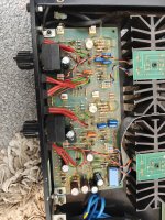
I have a HH VX-150 that I've finally finished cleaning up and refurbishing. A little while back I removed the VGA daughter boards as that was causing significant distortion.
I have been experimenting... I removed the input DC caps C1, C2, C7, and C8 and added links in their place. I also removed C1 and C12 on the drive board and wire linked it. I increased the DC caps C3 and C14 in the feedback path to a silly 820uf as that is what I had lying around.
After that the DC increased and settled to around 40mV so not too bad. (My input source is a very very low DC offset)
The most interesting thing was the bias. Lowering the bias adjusting pots VR3 and 6 lowered distortion. (I measured the distortion at 30Khz at 10mv in a 4ohm load to get a good picture of crossover distortion)
I measured current draw from mains and voltage between gate pins + and -. it was originally 800mv between these points. (I believe the VX450 specifies 800mv). The distortion measured 1.2% (at the above paragraph method of measuring). Lowering to the lowest possible on the pots this decreased down to 0.8%! Mains current draw is now 80mA
500mV @ 1 kHz distortion was 0.0035% not bad at all.
Top end sounds much better after lower bias.
The only issue is DC offset jumps around upto 2V after swirch off! That will cause pops and clicks and risk to compression drivers! DC caps on the output would sort that out.
Attachments

Risky !! An amp like this needs those components. Especially with FET's. I'm surprised it even worked after your experiment.I have been experimenting... I removed the input DC caps C1, C2, C7, and C8 and added links in their place.
Why not just replace them caps with the utmost quality replacements ?

Thanks. I have put the caps back in. DC offset now back to 1-2mV after adjustment of DC offset pots.
I tried again with bias adjustment. Ammeter in between one of the power rails. With the pots at their maximum resistance bias is 26mA this was the lowest distortion. Adjustment to around 120mA increased distortion.
I tried again with bias adjustment. Ammeter in between one of the power rails. With the pots at their maximum resistance bias is 26mA this was the lowest distortion. Adjustment to around 120mA increased distortion.
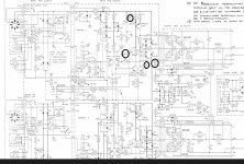
The HH's circuit topology is the same as my Sonance 260 , except it uses the "hitachi" topology to drive genuine Hitachi LATFETS.
Circled caps are it's compensation components. Almost the same as the Sonance . Lead 10pF/C4 , A shunt C31- 47p , etc.
You could simulate this simple topology to "tweak" its phase-bandwidth. The best way to "voice" the amp's circuit.
Simulated , you can even increase loop gain and re-compensate to maintain phase (stability margin) without killing the amp.
PS - all those small ceramics 10-47p are best as silver mica , the smallest pF change in them equates to a large response-stability change.
My 10pF's were 5-7p - way off ! I replaced with 15p and increased the VAS gain by 30%. Same "curve".
OS